Table of Contents
Contactors Wiring Diagram
Unlocking the Power of Contactors Wiring Diagram
Contactors play a crucial role in controlling electrical circuits, allowing for the efficient operation of various systems. A well-designed wiring diagram for contactors not only simplifies the installation process but also ensures optimal performance and safety. Understanding the intricacies of contactors wiring diagrams can empower electricians, engineers, and DIY enthusiasts to navigate complex electrical systems with confidence and precision. Let’s delve into the world of contactors wiring diagrams to unveil the keys to unlocking their full potential.
The Basics of Contactors Wiring Diagram
A contactor wiring diagram serves as a visual representation of how electrical components are interconnected within a circuit. It illustrates the connections between power sources, control devices, and load circuits, providing a roadmap for understanding and troubleshooting the system. By following the symbols and layout depicted in the wiring diagram, individuals can trace the flow of electricity and identify potential issues or modifications required for optimal functionality.
Key Components in a Contactors Wiring Diagram
When examining a contactors wiring diagram, several essential components stand out, each playing a distinct role in the circuit’s operation. These components include:
Contactors: These act as the main switching devices in the circuit, controlling the flow of electricity to the load.
Coil Terminals: Responsible for energizing the contactor to initiate the switching process.
Control Devices: Such as push buttons, switches, or sensors, which activate or deactivate the contactor based on predetermined conditions.
Load Circuits: The devices or equipment that receive power from the contactor to perform their intended functions.
Benefits of Using Contactors Wiring Diagram
Employing a well-structured wiring diagram for contactors offers several advantages in both installation and maintenance processes. Some key benefits include:
Clarity: Provides a clear and organized layout of the electrical connections, reducing the likelihood of errors during installation.
Efficiency: Streamlines troubleshooting procedures by offering a visual guide to identify and rectify faults promptly.
Safety: Ensures that all connections are made correctly, minimizing the risk of electrical hazards or malfunctions.
Practical Applications of Contactors Wiring Diagram
Contactors wiring diagrams find application in a wide range of industries and systems, including HVAC systems, industrial machinery, and automation processes. By adhering to the standards and conventions outlined in wiring diagrams, professionals can achieve seamless integration of contactors into complex electrical setups, guaranteeing reliable and efficient performance.
Conclusion
In conclusion, mastering the art of interpreting and creating contactors wiring diagrams is a valuable skill for anyone working with electrical systems. By grasping the fundamentals, understanding key components, and appreciating the benefits of using wiring diagrams, individuals can elevate their proficiency in handling contactors and ensuring the smooth operation of electrical circuits. Embrace the power of contactors wiring diagrams as your guide to unlocking the full potential of electrical systems.
Related to Contactors Wiring Diagram
- Connection Single Phase Motor Wiring Diagram Forward Reverse
- Contact Wiring Diagram
- Contactor Diagram Wiring Lighting
- Contactor Wiring Diagram
- Contactor Wiring Diagram Single Phase
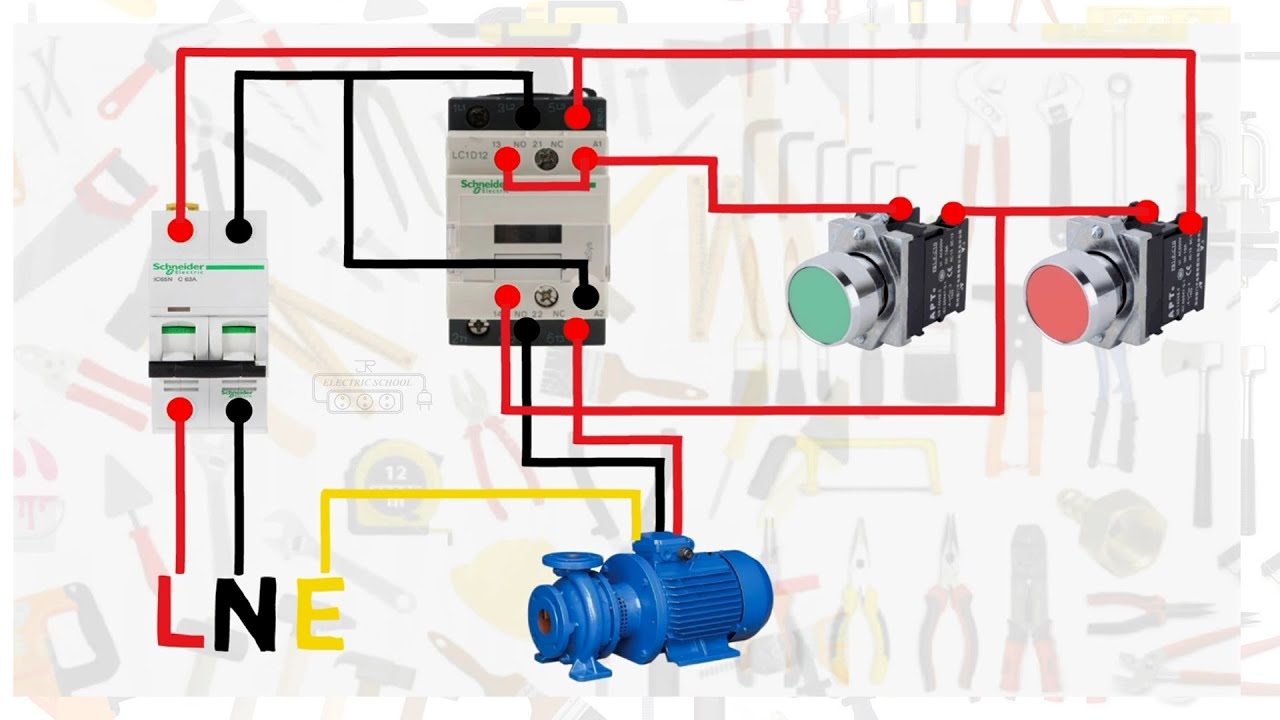
Single Phase Motor Connection With Magnetic Contactor Wiring Diagram YouTube
The image title is Single Phase Motor Connection With Magnetic Contactor Wiring Diagram YouTube, features dimensions of width 1280 px and height 720 px, with a file size of 1280 x 720 px. This image image/jpeg type visual are source from www.youtube.com.
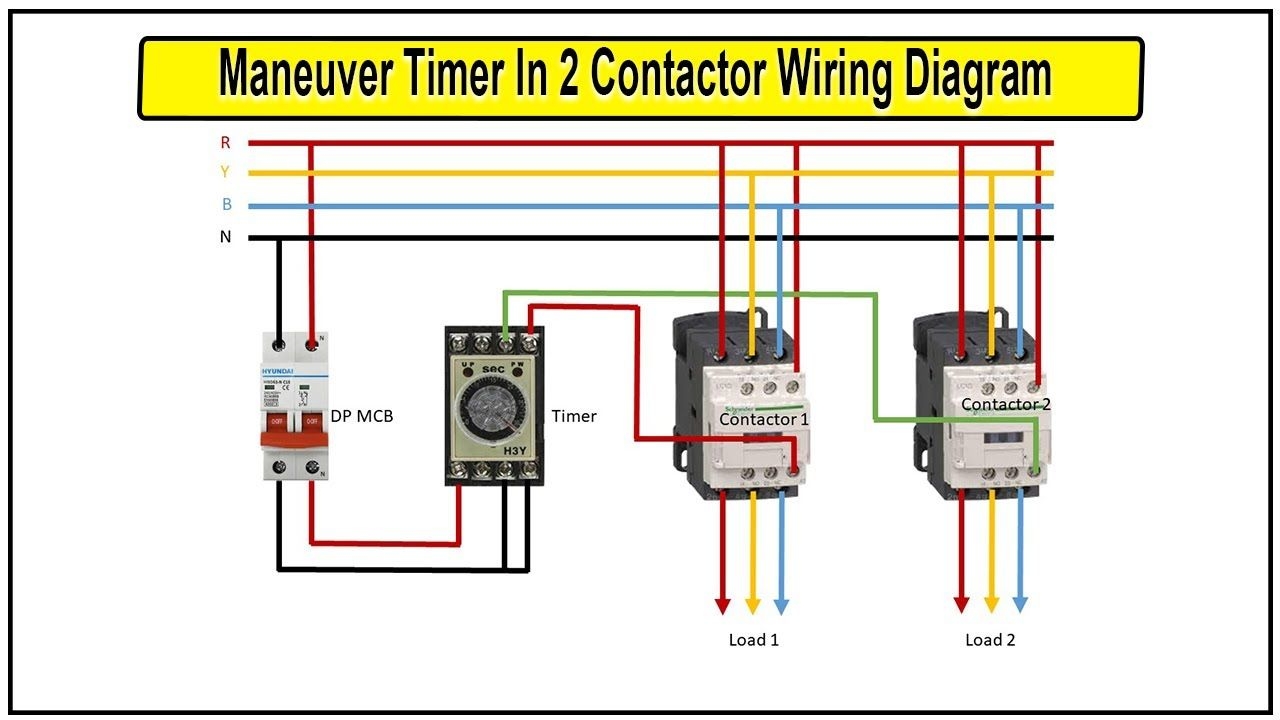
Timer In Contactor Wiring Diagram Contactor Wiring Diagram With Timer Timer Switch Wiring Timer Diagram Breakers
The image title is Timer In Contactor Wiring Diagram Contactor Wiring Diagram With Timer Timer Switch Wiring Timer Diagram Breakers, features dimensions of width 1280 px and height 720 px, with a file size of 1280 x 720 px. This image image/jpeg type visual are source from www.pinterest.com.
Single Phase Motor Connection With Magnetic Contactor Wiring Diagram YouTube
The image title is Single Phase Motor Connection With Magnetic Contactor Wiring Diagram YouTube, features dimensions of width 1280 px and height 720 px, with a file size of 1280 x 720. This image image/jpeg type visual are source from www.youtube.com.
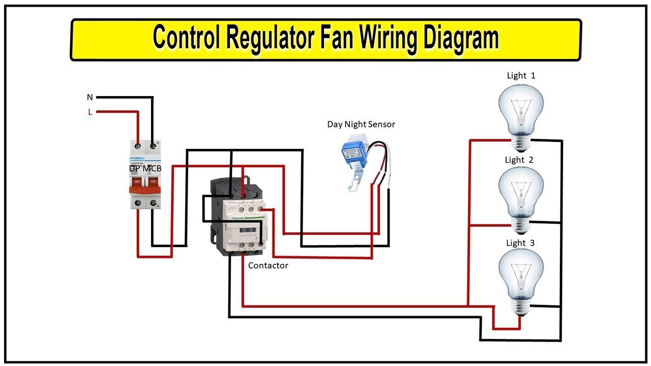
Day Night Sensor Wiring Diagram Photocell Sensor Connection Day Night Sensor Wiring Diagram Sensor Breakers Night
The image title is Day Night Sensor Wiring Diagram Photocell Sensor Connection Day Night Sensor Wiring Diagram Sensor Breakers Night, features dimensions of width 1280 px and height 720 px, with a file size of 1280 x 720. This image image/jpeg type visual are source from www.pinterest.com.
How To Make Contactor Wiring With Holding Circuit Diagram Contactor YouTube
The image title is How To Make Contactor Wiring With Holding Circuit Diagram Contactor YouTube, features dimensions of width 1280 px and height 720 px, with a file size of 1280 x 720. This image image/jpeg type visual are source from www.youtube.com
How To Wire A Contactor 8 Steps With Pictures WikiHow
The image title is How To Wire A Contactor 8 Steps With Pictures WikiHow, features dimensions of width 1200 px and height 900 px, with a file size of 1200 x 900. This image image/jpeg type visual are source from www.wikihow.com.
Single Phase 2 Pole Contactor Wiring Diagram Electrical Diagram Electrical Circuit Diagram Pole
The image title is Single Phase 2 Pole Contactor Wiring Diagram Electrical Diagram Electrical Circuit Diagram Pole, features dimensions of width 1661 px and height 1157 px, with a file size of 1661 x 1157. This image image/png type visual are source from www.pinterest.com.
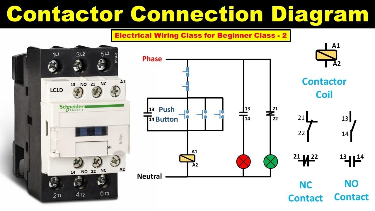
How To Do Contactor Wiring Electrical Wiring Class For Beginner Class 2 TheElectricalGuy YouTube
The image title is How To Do Contactor Wiring Electrical Wiring Class For Beginner Class 2 TheElectricalGuy YouTube, features dimensions of width 1280 px and height 720 px, with a file size of 1280 x 720.
The images on this page, sourced from Google for educational purposes, may be copyrighted. If you own an image and wish its removal or have copyright concerns, please contact us. We aim to promptly address these issues in compliance with our copyright policy and DMCA standards. Your cooperation is appreciated.
Related Keywords to Contactors Wiring Diagram:
contactor wiring diagram a1 a2,contactor wiring diagram ac,contactor wiring diagram pdf,contactor wiring diagram single phase,contactors wiring diagram


