Table of Contents
The Ultimate Guide to Contactor Wiring Diagram
Contactor wiring diagrams are essential tools for anyone working with electrical systems. Whether you’re a seasoned electrician or a DIY enthusiast, understanding how contactors work and how to wire them correctly is crucial for the safety and efficiency of any electrical project. In this comprehensive guide, we will delve into the intricacies of contactor wiring diagrams, unraveling the complexities to provide you with a clear understanding of their importance and how to effectively utilize them in your electrical installations.
The Basics of Contactors
Before we dive into the world of contactor wiring diagrams, let’s first establish a solid foundation by understanding what contactors are and how they function. Contactors are electrical devices used to control the flow of electricity in a circuit. They are essentially switches that are activated by an electrical signal, allowing them to open or close the circuit as needed. Contactors are commonly used in industrial settings to control large motors, lighting systems, and other heavy-duty electrical equipment.
Key Components of a Contactor
A typical contactor consists of several key components, each playing a crucial role in its operation. These components include:
- Coil: The coil is the part of the contactor that generates the magnetic field necessary to actuate the contacts.
- Contacts: These are the switch-like components that open and close the circuit when the contactor is activated.
- Auxiliary Contacts: These additional contacts can be used for auxiliary functions such as signaling or interlocking with other devices.
- Enclosure: The enclosure houses the internal components of the contactor, providing protection from environmental factors.
Understanding Contactor Wiring Diagrams
Contactor wiring diagrams serve as roadmaps for installing and troubleshooting contactors in electrical systems. These diagrams provide a visual representation of how the various components of a contactor are connected, helping electricians and installers follow the correct wiring sequence. By interpreting a contactor wiring diagram, one can easily identify the connections between the coil, contacts, power supply, and control circuit, ensuring that the contactor functions as intended.
Interpreting Wiring Symbols
When reading a contactor wiring diagram, it’s essential to understand the various symbols used to represent different components and connections. Some common symbols you may encounter include:
- Coil: Represents the coil of the contactor, usually denoted by a zigzag line.
- Contacts: Shown as two parallel lines that intersect when the contacts are closed.
- Control Circuit: Indicates the wiring for the control circuit that activates the contactor.
- Power Supply: Represents the incoming power source that energizes the contactor.
Step-by-Step Wiring Instructions
To effectively wire a contactor, follow these step-by-step instructions:
- Identify the coil terminals and connect them to the control circuit.
- Connect the power supply to the main contacts of the contactor.
- Ensure proper grounding and insulation for safety.
- Test the contactor to verify proper operation.
By following these instructions and referencing a contactor wiring diagram, you can confidently install and troubleshoot contactors in any electrical system.
Related to Contactor Wiring Diagram
- Condenser Wiring Diagram
- Connection 3 Speed Fan Motor Wiring Diagram
- Connection Single Phase Motor Wiring Diagram Forward Reverse
- Contact Wiring Diagram
- Contactor Diagram Wiring Lighting
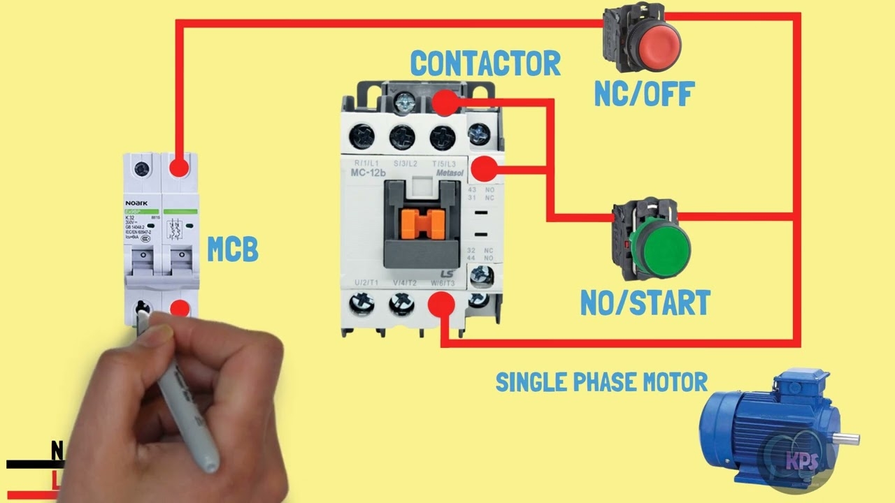
Single Phase Motor Connection With Magnetic Contactor Wiring Diagram YouTube
The image title is Single Phase Motor Connection With Magnetic Contactor Wiring Diagram YouTube, features dimensions of width 1280 px and height 720 px, with a file size of 1280 x 720 px. This image image/jpeg type visual are source from m.youtube.com.
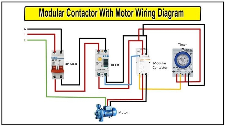
How To Make Modular Contactor With Motor Wiring Diagram Magnetic Contactor Wiring Diagram Modular Diagram Wire
The image title is How To Make Modular Contactor With Motor Wiring Diagram Magnetic Contactor Wiring Diagram Modular Diagram Wire, features dimensions of width 736 px and height 414 px, with a file size of 736 x 414 px. This image image/jpeg type visual are source from www.pinterest.com.
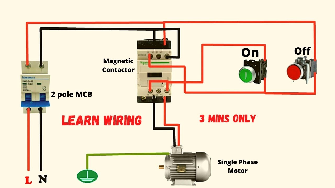
Single Phase Motor Connection With Magnetic Contactor Wiring Diagram YouTube
The image title is Single Phase Motor Connection With Magnetic Contactor Wiring Diagram YouTube, features dimensions of width 1280 px and height 720 px, with a file size of 1280 x 720. This image image/jpeg type visual are source from www.youtube.com.
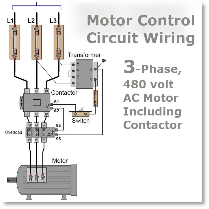
Electric Contactor Wiring In Electric Motors Relectric
The image title is Electric Contactor Wiring In Electric Motors Relectric, features dimensions of width 724 px and height 724 px, with a file size of 724 x 724. This image image/jpeg type visual are source from www.relectric.com
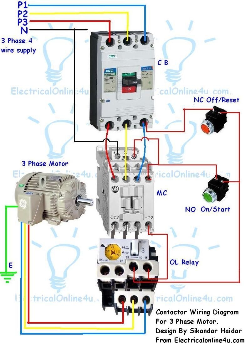
6372A1A Contactor Wiring Diagram Single Phase Circuit Diagram Electrical Circuit Diagram Electrical Wiring Diagram
The image title is 6372A1A Contactor Wiring Diagram Single Phase Circuit Diagram Electrical Circuit Diagram Electrical Wiring Diagram, features dimensions of width 799 px and height 1114 px, with a file size of 799 x 1114. This image image/jpeg type visual are source from www.pinterest.com.
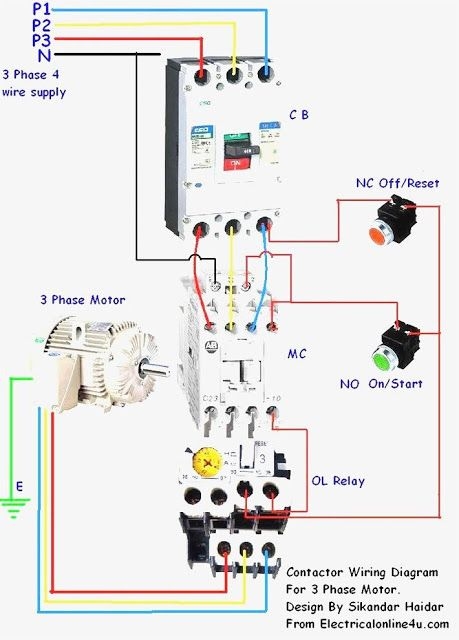
Magnetic Contactor Connection Diagram Magnetic Contactor Connection Diagram With A Electrical Circuit Diagram Electrical Wiring Diagram Home Electrical Wiring
The image title is Magnetic Contactor Connection Diagram Magnetic Contactor Connection Diagram With A Electrical Circuit Diagram Electrical Wiring Diagram Home Electrical Wiring, features dimensions of width 459 px and height 640 px, with a file size of 459 x 640. This image image/jpeg type visual are source from www.pinterest.com.
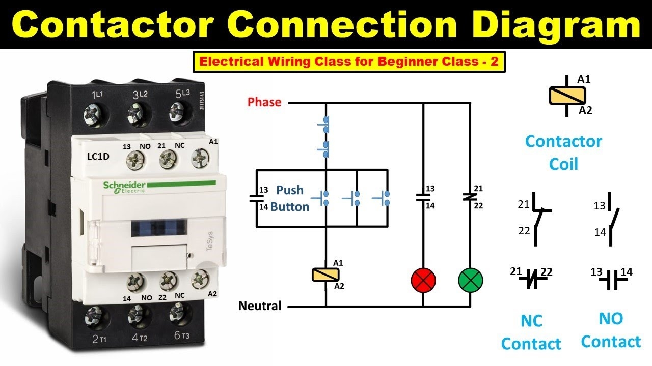
How To Do Contactor Wiring Electrical Wiring Class For Beginner Class 2 TheElectricalGuy YouTube
The image title is How To Do Contactor Wiring Electrical Wiring Class For Beginner Class 2 TheElectricalGuy YouTube, features dimensions of width 1280 px and height 720 px, with a file size of 1280 x 720.
The images on this page, sourced from Google for educational purposes, may be copyrighted. If you own an image and wish its removal or have copyright concerns, please contact us. We aim to promptly address these issues in compliance with our copyright policy and DMCA standards. Your cooperation is appreciated.
Related Keywords to Contactor Wiring Diagram:
contactor wiring diagram,contactor wiring diagram a1 a2,contactor wiring diagram ac,contactor wiring diagram pdf,contactor wiring diagram single phase
