Table of Contents
Exploring the Wonders of Contactor Diagram Wiring Lighting
Exploring the Wonders of Contactor Diagram Wiring Lighting
Contactor diagram wiring lighting is a crucial aspect of any electrical system, providing the foundation for efficient and effective illumination in various settings. Whether in residential, commercial, or industrial spaces, the proper installation and configuration of contactor wiring diagrams can greatly enhance the functionality and aesthetics of lighting setups. In this article, we delve into the intricacies of contactor diagram wiring lighting, uncovering its significance and exploring the various elements that contribute to its seamless operation.
The Basics of Contactor Diagram Wiring
At its core, contactor diagram wiring involves the use of electrical contactors to control the flow of electricity to lighting fixtures. Contactors are electromechanical devices that enable the switching of electrical circuits, allowing for the automation and control of lighting systems. By utilizing contactor wiring diagrams, electricians and lighting designers can create intricate setups that cater to specific requirements and preferences.
Key Components of Contactor Diagram Wiring
In a typical contactor diagram wiring setup, several key components play vital roles in ensuring the smooth operation of lighting systems. These components include:
Contactor: The main switching device that controls the flow of electricity to lighting fixtures.
Coil: The electromagnetic coil that activates the contactor when energized.
Contacts: The points where electrical connections are made or broken to control the circuit.
Overload Relay: A protective device that trips in case of excessive current flow, safeguarding the system from damage.
Importance of Proper Contactor Diagram Wiring
Proper contactor diagram wiring is essential for ensuring the safety, efficiency, and longevity of lighting systems. By following industry standards and best practices, electricians can create reliable setups that minimize the risk of electrical faults and ensure optimal performance. Additionally, well-designed contactor wiring diagrams offer flexibility and ease of maintenance, allowing for seamless modifications and upgrades as needed.
Benefits of Efficient Contactor Diagram Wiring
Efficient contactor diagram wiring offers a range of benefits, including:
Enhanced Energy Efficiency: By controlling the operation of lighting fixtures, contactor wiring diagrams help minimize energy wastage and reduce utility costs.
Improved Safety: Properly configured contactor setups enhance the safety of electrical systems, reducing the risk of short circuits and electrical hazards.
Customized Control: Contactors allow for customized control of lighting systems, enabling dimming, scheduling, and other advanced functionalities.
Exploring Advanced Applications of Contactor Diagram Wiring
Beyond basic setups, contactor diagram wiring can be utilized in a variety of advanced applications to achieve specific lighting goals. From smart lighting solutions to complex automation schemes, the versatility of contactor wiring diagrams opens up a world of possibilities for innovative lighting designs.
Case Studies and Examples
To better understand the practical applications of contactor diagram wiring lighting, let’s explore some real-world case studies and examples where this technology has been successfully implemented:
Industrial Warehouse Lighting: Contactor wiring diagrams are used to control high-bay lighting fixtures in large warehouses, optimizing energy usage and ensuring adequate illumination.
Outdoor Landscape Lighting: Contactors enable the automation of outdoor lighting systems, allowing for scheduled operation and enhanced security.
Commercial Office Lighting: With sophisticated contactor setups, commercial offices can achieve dynamic lighting scenes that adapt to different work environments and preferences.
Conclusion
In conclusion, contactor diagram wiring lighting is a fundamental aspect of modern electrical systems, offering unparalleled control and flexibility in lighting design. By mastering the principles of contactor wiring diagrams and harnessing their potential, electricians and lighting professionals can create innovative and efficient lighting solutions that elevate the ambiance and functionality of any space.
Related to Contactor Diagram Wiring Lighting
- Condensate Pump Wiring Diagram
- Condenser Wiring Diagram
- Connection 3 Speed Fan Motor Wiring Diagram
- Connection Single Phase Motor Wiring Diagram Forward Reverse
- Contact Wiring Diagram
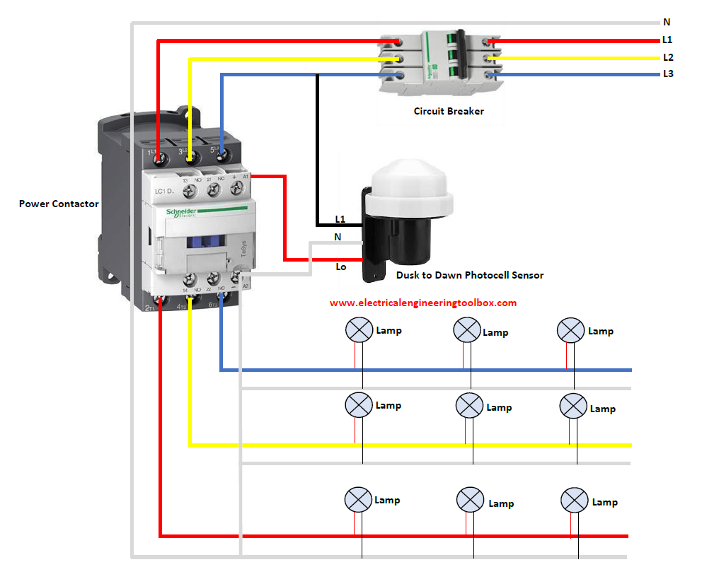
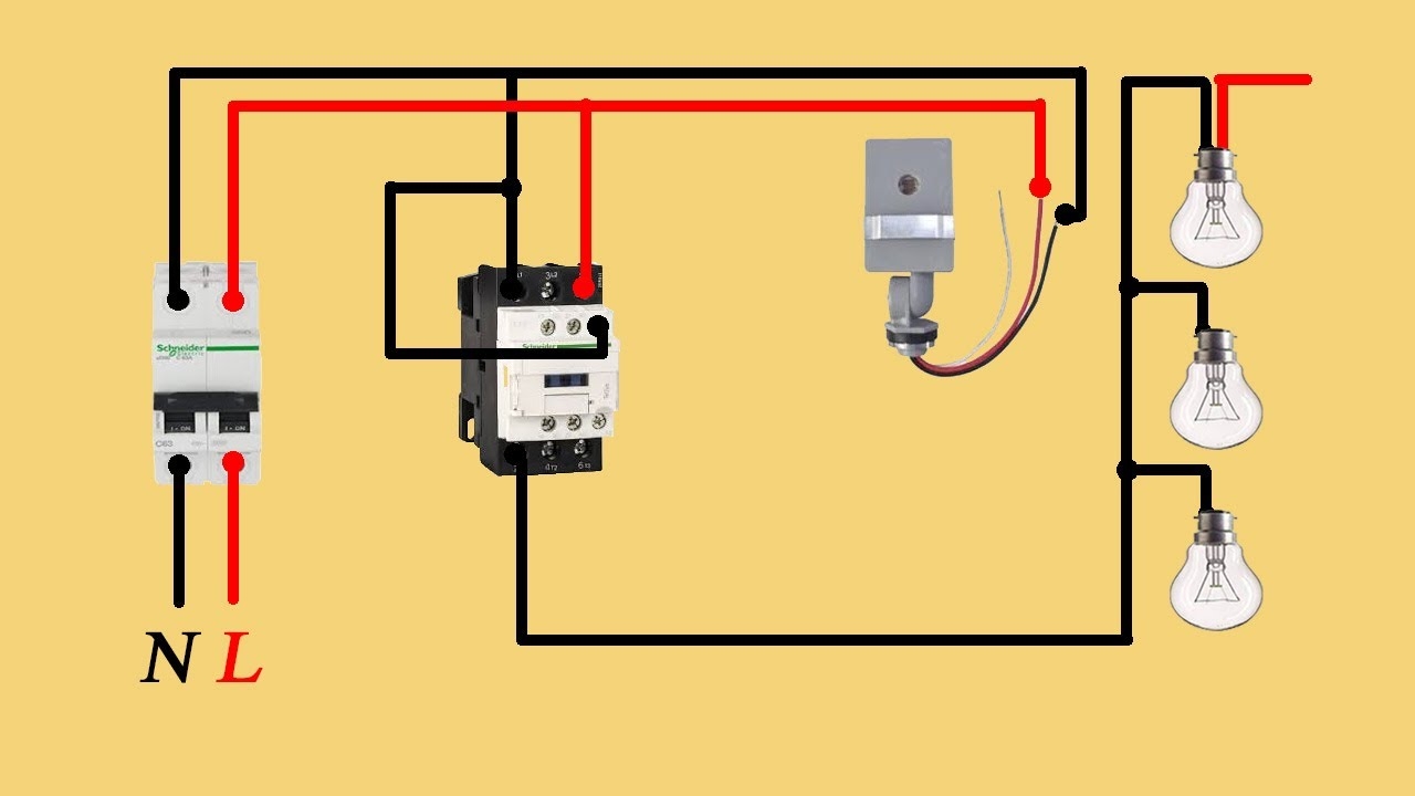
How To Wire A Photocell Switch To Lighting Loads With A Contactor Learning Electrical Engineering
The image title is How To Wire A Photocell Switch To Lighting Loads With A Contactor Learning Electrical Engineering, features dimensions of width 992 px and height 802 px, with a file size of 992 x 802 px. This image image/png type visual are source from www.electricalengineeringtoolbox.com.
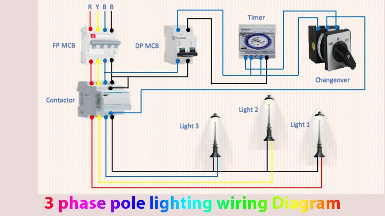
3 Phase Pole Lighting Wiring Diagram Light Manual Light Automatic YouTube
The image title is 3 Phase Pole Lighting Wiring Diagram Light Manual Light Automatic YouTube, features dimensions of width 1280 px and height 720 px, with a file size of 1280 x 720 px. This image image/jpeg type visual are source from m.youtube.com.
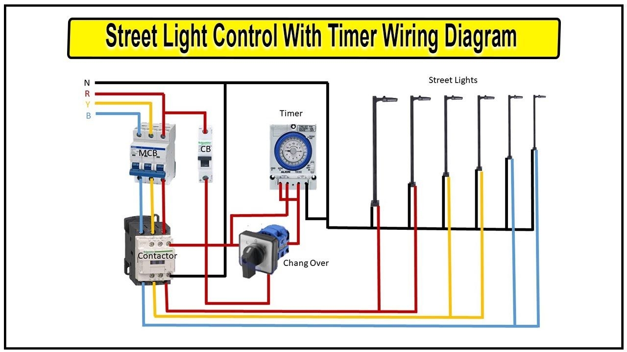
How To Make Street Light Control With Timer Wiring Diagram Timer Connection For Street Light Street Light Light Control Traffic Light
The image title is How To Make Street Light Control With Timer Wiring Diagram Timer Connection For Street Light Street Light Light Control Traffic Light, features dimensions of width 1280 px and height 720 px, with a file size of 1280 x 720. This image image/jpeg type visual are source from www.pinterest.com.
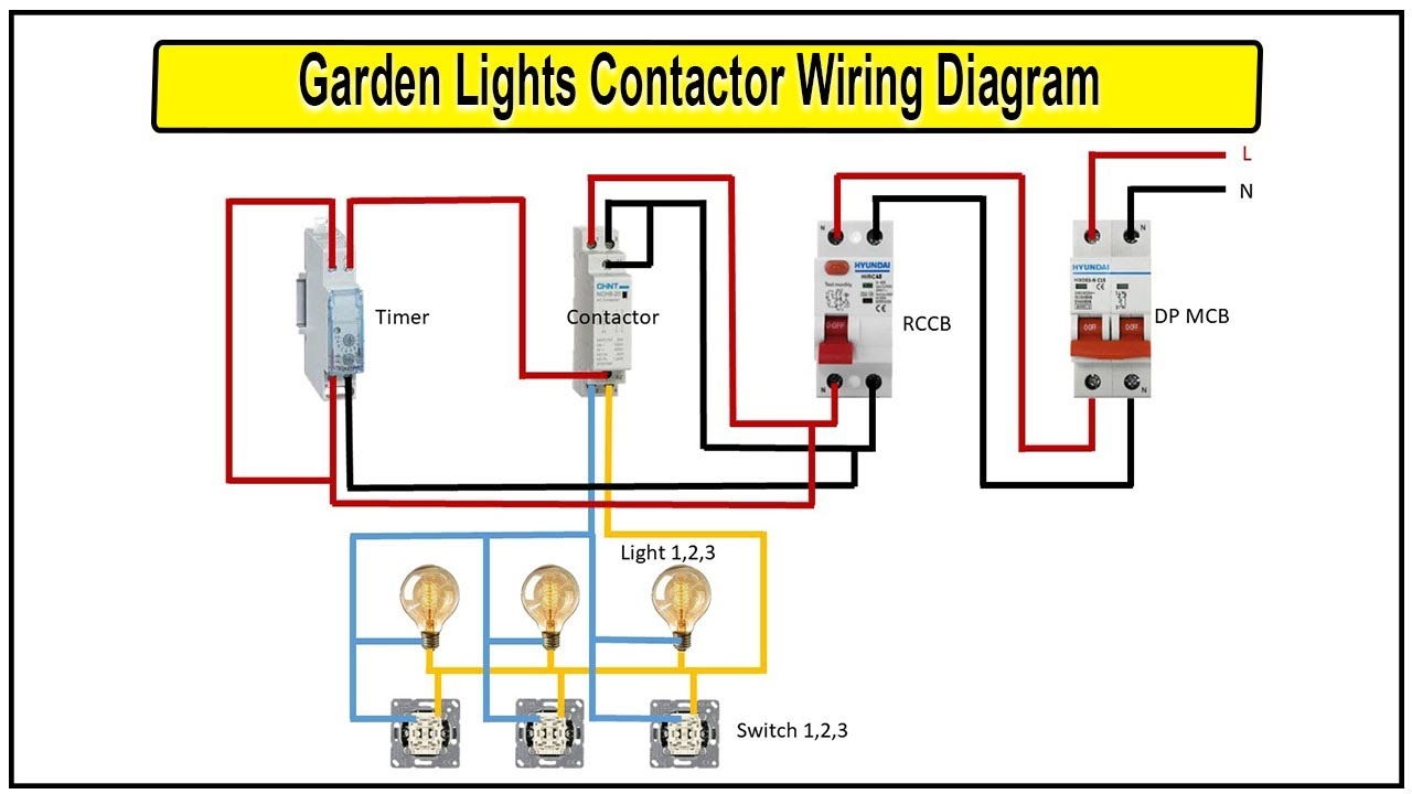
How To Make Garden Lights Contactor Wiring Diagram Lighting Timer And Contactor Wiring Diagram YouTube
The image title is How To Make Garden Lights Contactor Wiring Diagram Lighting Timer And Contactor Wiring Diagram YouTube, features dimensions of width 1280 px and height 720 px, with a file size of 1280 x 720. This image image/jpeg type visual are source from m.youtube.com.
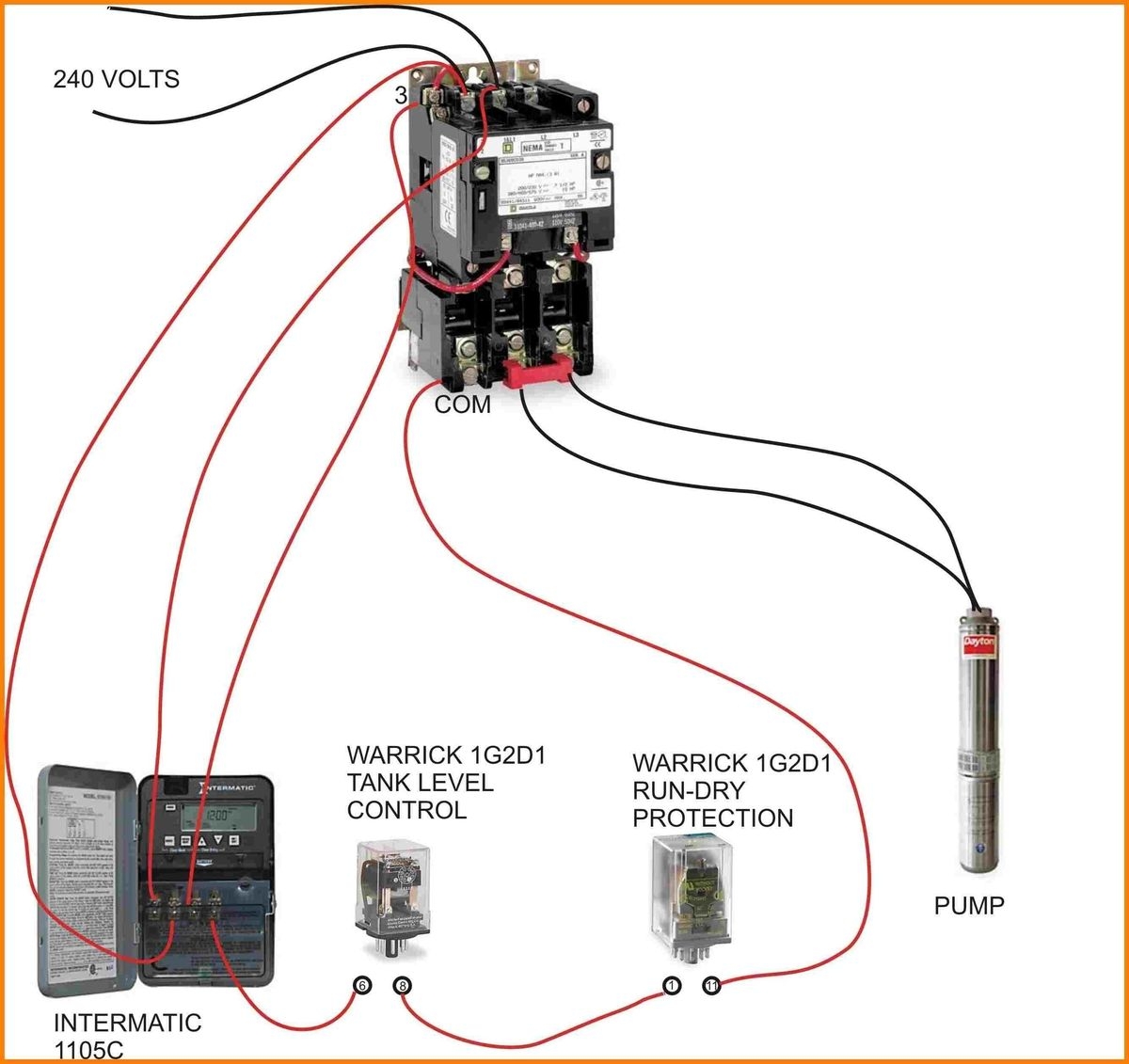
Magnetic Contactor Wiring Diagram Electrical Circuit Diagram Electrical Wiring Diagram Well Pump
The image title is Magnetic Contactor Wiring Diagram Electrical Circuit Diagram Electrical Wiring Diagram Well Pump, features dimensions of width 1200 px and height 1131 px, with a file size of 1200 x 1131. This image image/jpeg type visual are source from www.pinterest.com
Photocell Sensor Connection With A Contactor YouTube
The image title is Photocell Sensor Connection With A Contactor YouTube, features dimensions of width 1280 px and height 720 px, with a file size of 1280 x 720. This image image/jpeg type visual are source from www.youtube.com.
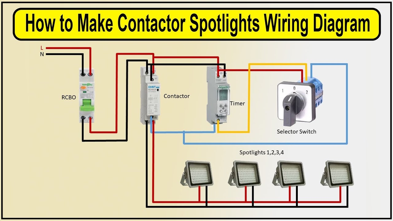
How To Make Contactor Spotlights Wiring Diagram Wire Up A Lighting Contactor YouTube
The image title is How To Make Contactor Spotlights Wiring Diagram Wire Up A Lighting Contactor YouTube, features dimensions of width 1280 px and height 720 px, with a file size of 1280 x 720. This image image/jpeg type visual are source from www.youtube.com.
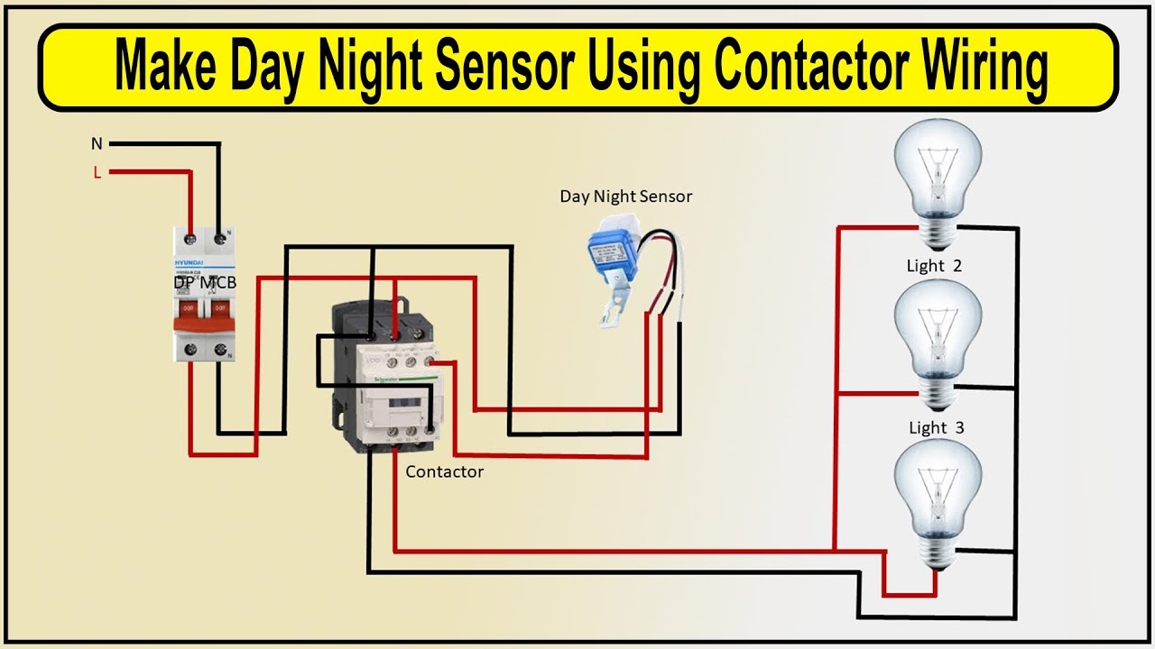
How To Make Day Night Sensor Using Contactor Wiring Diagram Photocell Sensor Connection YouTube
The image title is How To Make Day Night Sensor Using Contactor Wiring Diagram Photocell Sensor Connection YouTube, features dimensions of width 1280 px and height 720 px, with a file size of 1280 x 720.
The images on this page, sourced from Google for educational purposes, may be copyrighted. If you own an image and wish its removal or have copyright concerns, please contact us. We aim to promptly address these issues in compliance with our copyright policy and DMCA standards. Your cooperation is appreciated.
Related Keywords to Contactor Diagram Wiring Lighting:
abb lighting contactor wiring diagram,contactor wiring diagram lighting,eaton lighting contactor wiring diagram,lighting contactor wiring diagram pdf,lighting contactor wiring diagram with timer
