Table of Contents
Exploring the Value of Condensate Pump Wiring Diagram
The Importance of Condensate Pump Wiring Diagram
Condensate pumps play a crucial role in HVAC systems by removing excess water that accumulates during the cooling process. To ensure these pumps function efficiently, proper wiring is essential. A condensate pump wiring diagram serves as a detailed guide that outlines the electrical connections required for the pump to operate effectively.
Understanding the Components
Before delving into the wiring diagram, it’s important to familiarize yourself with the key components of a condensate pump. These typically include a reservoir, a float switch, a pump, and various electrical connections. Each component plays a specific role in the pump’s operation and must be correctly wired to ensure optimal performance.
Interpreting the Wiring Diagram
A condensate pump wiring diagram provides a visual representation of how each component should be connected to the power source and to one another. By following the diagram carefully, HVAC technicians can avoid errors and ensure that the pump functions reliably. Understanding the symbols and labels used in the diagram is crucial for accurate wiring.
Steps to Wire a Condensate Pump
Start by studying the wiring diagram provided by the pump manufacturer.
Identify the power source and ensure it meets the voltage requirements of the pump.
Connect the wires from the float switch to the designated terminals on the pump.
Secure all connections with appropriate connectors to prevent loose wiring.
Test the pump to verify that it is operating correctly before installation.
Tips for Efficient Wiring
Use only high-quality wiring materials to prevent electrical issues.
Label all wires and connections to facilitate troubleshooting and maintenance in the future.
Consult the pump manufacturer’s guidelines for specific wiring instructions.
Benefits of Proper Wiring
Ensuring that a condensate pump is correctly wired has several advantages. It reduces the risk of malfunctions or breakdowns, prolongs the pump’s lifespan, and enhances the overall efficiency of the HVAC system. Proper wiring also contributes to safety by minimizing the potential for electrical hazards.
Conclusion
In conclusion, a condensate pump wiring diagram is a valuable tool that guides HVAC technicians in correctly connecting the components of a condensate pump. By following the diagram accurately and adhering to best practices for wiring, technicians can optimize the performance and reliability of these essential HVAC components.
Related to Condensate Pump Wiring Diagram
- Compressor Diagram Wiring
- Compressor Start Relay Wiring Diagram
- Compressor Wiring Diagram
- Compressor Wiring Diagram Single Phase
- Computer Power Supply Wiring Diagram
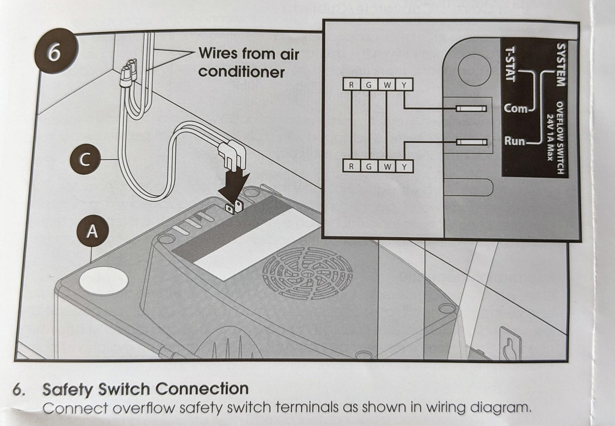
Where Do I Connect Condensate Pump Safety Switch Com And Run Wires On My Aprilaire Dehumidifier Interface Module R Hvacadvice
The image title is Where Do I Connect Condensate Pump Safety Switch Com And Run Wires On My Aprilaire Dehumidifier Interface Module R Hvacadvice, features dimensions of width 2560 px and height 1776 px, with a file size of 2594 x 1800 px. This image image/jpeg type visual are source from www.reddit.com.
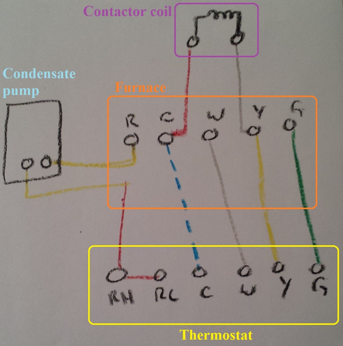
Hvac Help Installing New Thermostat Home Improvement Stack Exchange
The image title is Hvac Help Installing New Thermostat Home Improvement Stack Exchange, features dimensions of width 1120 px and height 1130 px, with a file size of 1120 x 1130 px. This image image/jpeg type visual are source from diy.stackexchange.com.
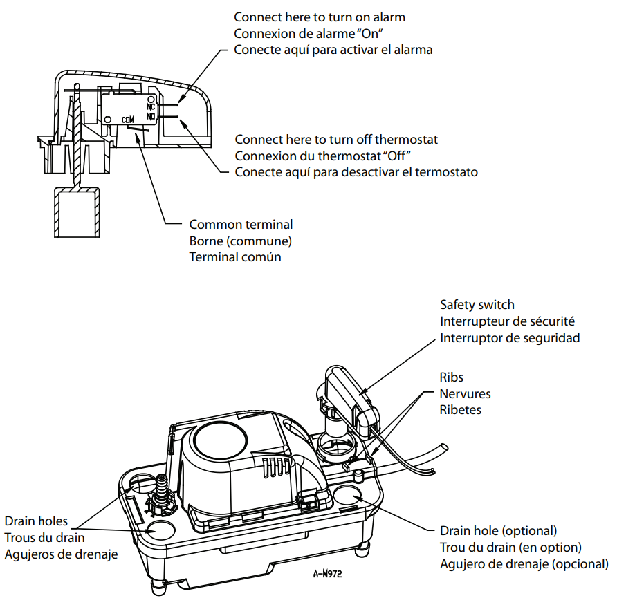
Electrical How To Connect A Safety Overflow Switch To Turn Off A Wall Outlet Home Improvement Stack Exchange
The image title is Electrical How To Connect A Safety Overflow Switch To Turn Off A Wall Outlet Home Improvement Stack Exchange, features dimensions of width 905 px and height 878 px, with a file size of 905 x 878. This image image/png type visual are source from diy.stackexchange.com.
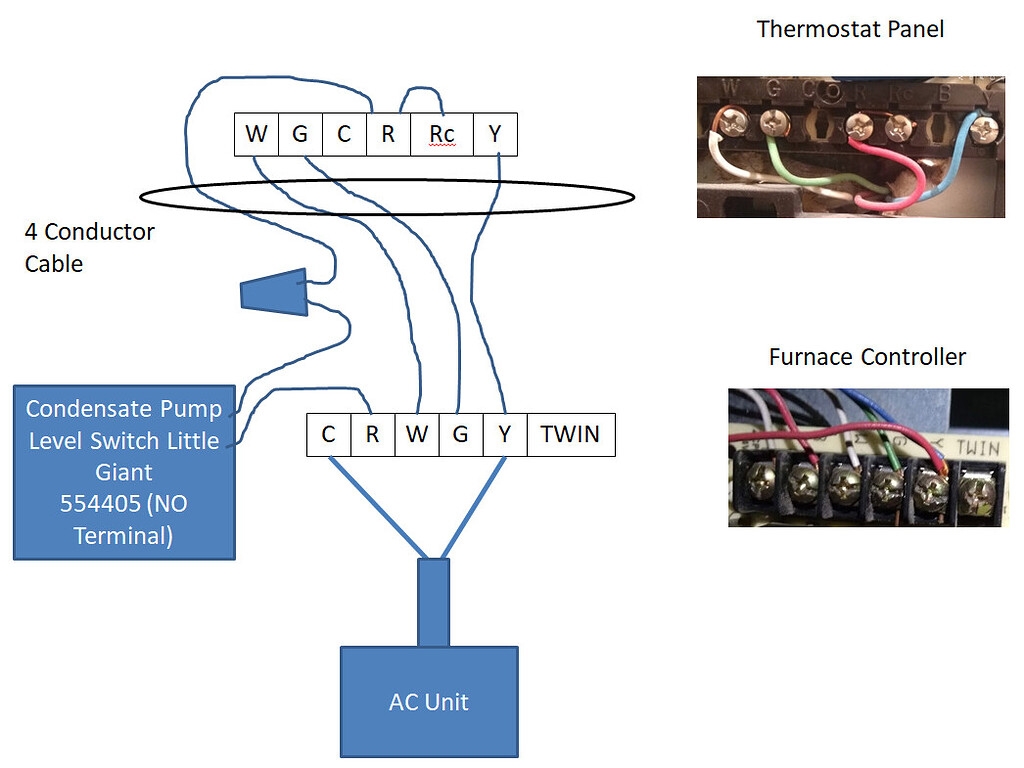
Wyze Thermostat Wiring Question Home Wyze Forum
The image title is Wyze Thermostat Wiring Question Home Wyze Forum, features dimensions of width 1024 px and height 768 px, with a file size of 1024 x 768. This image image/jpeg type visual are source from forums.wyze.com.
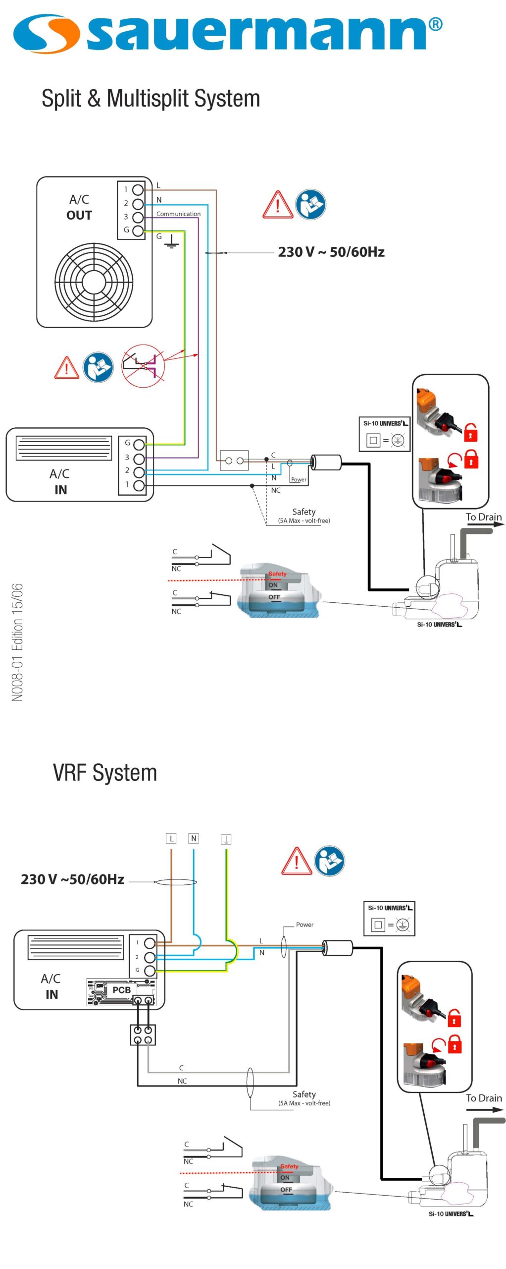
Connecting A Mini Pump Alarm Circuit Why It Matters And How To Do It Sauermann Group
The image title is Connecting A Mini Pump Alarm Circuit Why It Matters And How To Do It Sauermann Group, features dimensions of width 1022 px and height 2560 px, with a file size of 2145 x 5374. This image image/jpeg type visual are source from sauermanngroup.com
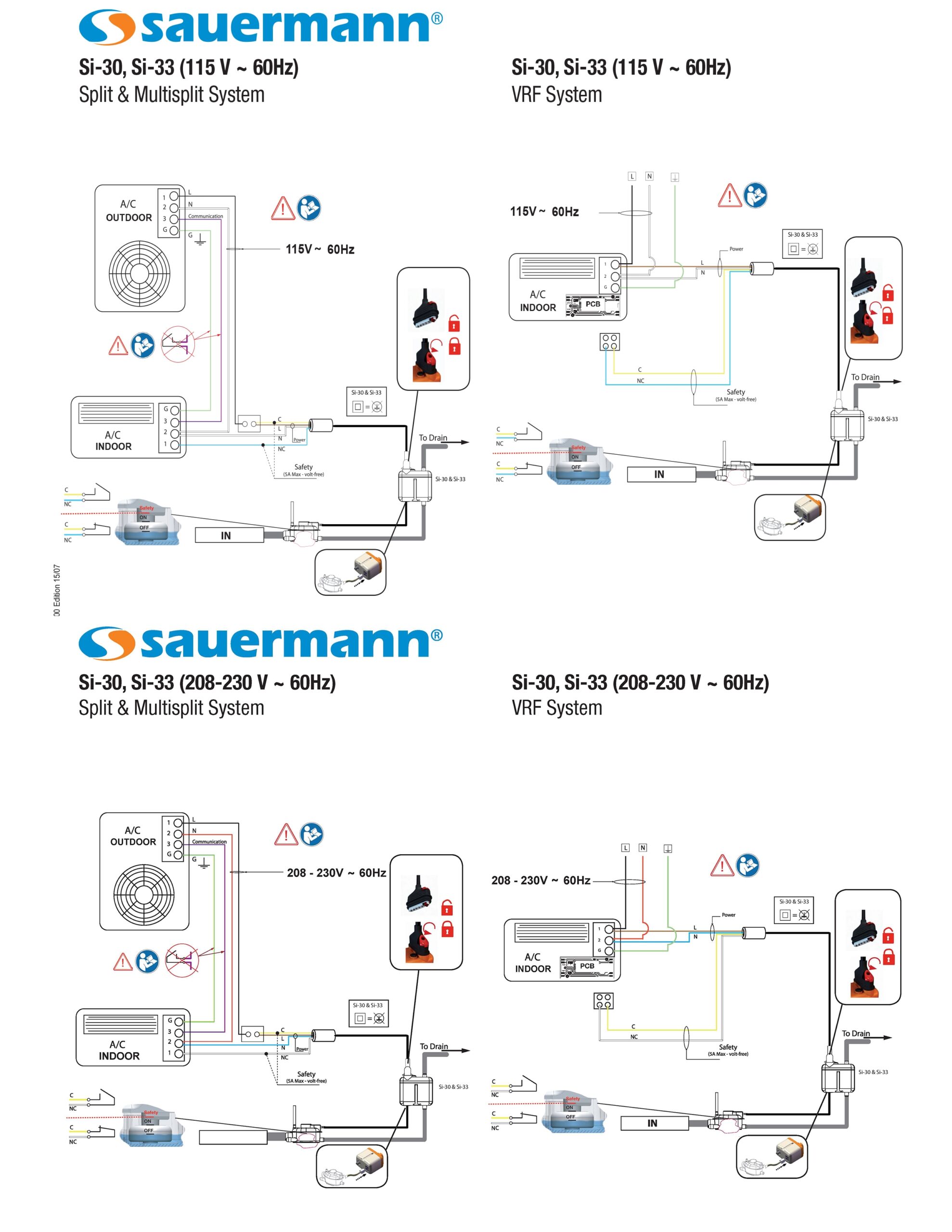
Connecting A Mini Pump Alarm Circuit Why It Matters And How To Do It Sauermann Group
The image title is Connecting A Mini Pump Alarm Circuit Why It Matters And How To Do It Sauermann Group, features dimensions of width 1978 px and height 2560 px, with a file size of 2550 x 3300. This image image/jpeg type visual are source from sauermanngroup.com.
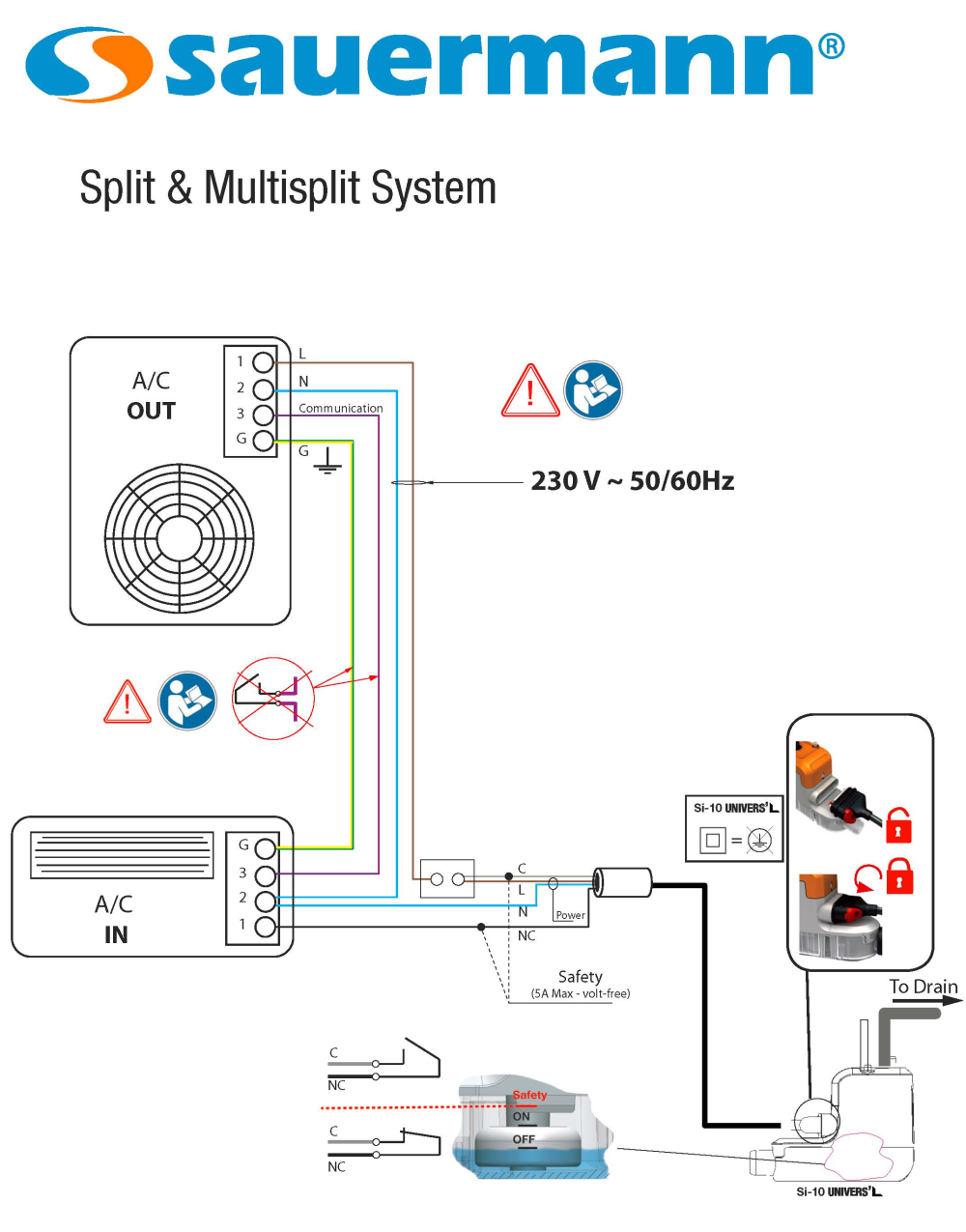
Connecting A Mini Pump Alarm Circuit Why It Matters And How To Do It Sauermann Group
The image title is Connecting A Mini Pump Alarm Circuit Why It Matters And How To Do It Sauermann Group, features dimensions of width 1000 px and height 1275 px, with a file size of 1000 x 1275. This image image/png type visual are source from sauermanngroup.com.
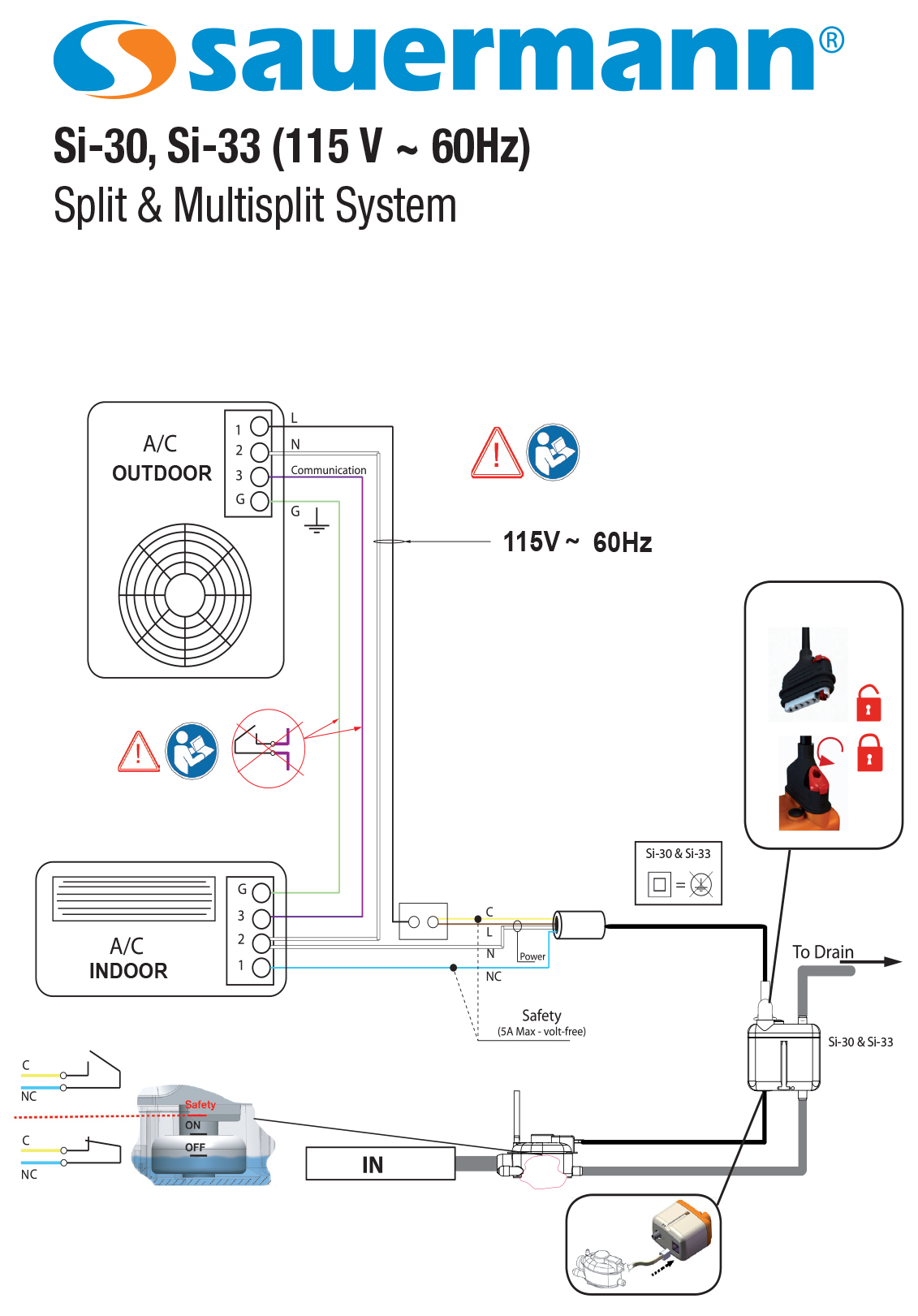
Connecting A Mini Pump Alarm Circuit Why It Matters And How To Do It Sauermann Group
The image title is Connecting A Mini Pump Alarm Circuit Why It Matters And How To Do It Sauermann Group, features dimensions of width 1131 px and height 1621 px, with a file size of 1131 x 1621.
The images on this page, sourced from Google for educational purposes, may be copyrighted. If you own an image and wish its removal or have copyright concerns, please contact us. We aim to promptly address these issues in compliance with our copyright policy and DMCA standards. Your cooperation is appreciated.
Related Keywords to Condensate Pump Wiring Diagram:
aspen condensate pump wiring diagram,condensate pump installation diagram,condensate pump wiring diagram,grundfos condensate pump wiring diagram,refco condensate pump wiring diagram
