Table of Contents
The Ultimate Guide to Compressor Wiring Diagrams
The Ultimate Guide to Compressor Wiring Diagrams
When it comes to understanding the intricate workings of HVAC systems, having a clear comprehension of compressor wiring diagrams is paramount. A compressor wiring diagram serves as a roadmap for technicians, guiding them through the complex network of electrical connections within an HVAC unit. By unraveling the mysteries of compressor wiring diagrams, technicians can troubleshoot issues effectively, optimize system performance, and ensure the smooth operation of heating and cooling systems. Let’s delve into the world of compressor wiring diagrams and explore their significance in the realm of HVAC technology.
The Basics of Compressor Wiring Diagrams
Compressor wiring diagrams are detailed schematics that illustrate the electrical components and their interconnections within a compressor unit. These diagrams provide a visual representation of the wiring layout, including the power supply, capacitors, relays, and other essential components. By studying a compressor wiring diagram, technicians can identify the different wires, terminals, and connections, enabling them to diagnose issues accurately and make necessary repairs.
Key Components in a Compressor Wiring Diagram
Power supply connections
Start and run capacitors
Relays and contactors
Thermostat connections
Safety switches
Importance of Understanding Compressor Wiring Diagrams
A thorough understanding of compressor wiring diagrams is essential for HVAC technicians to troubleshoot problems efficiently and ensure the proper functioning of HVAC systems. By following the wiring diagram, technicians can trace the flow of electricity, check for faulty connections, and pinpoint the root cause of malfunctions. Whether it’s a compressor not starting, a motor not running, or an inefficient cooling system, a comprehensive grasp of wiring diagrams is indispensable for resolving issues promptly.
Benefits of Using Compressor Wiring Diagrams
Facilitates troubleshooting and diagnostics
Ensures correct installation and wiring
Prevents electrical hazards and malfunctions
Improves system performance and efficiency
Interpreting Compressor Wiring Diagrams
Interpreting a compressor wiring diagram requires familiarity with electrical symbols, wire color codes, and circuit configurations. By deciphering the symbols and codes within the diagram, technicians can decipher the wiring connections, identify potential issues, and follow proper procedures for repairs and maintenance. With a keen eye for detail and a thorough understanding of electrical principles, technicians can navigate compressor wiring diagrams with confidence and precision.
Common Symbols and Codes in Compressor Wiring Diagrams
Wire colors (e.g., red for power, black for ground)
Symbols for capacitors, relays, and switches
Terminal labels (e.g., C, R, S, L)
Wire numbering and connections
Conclusion
In conclusion, a compressor wiring diagram is a vital tool for HVAC technicians, providing a roadmap to navigate the intricate electrical systems within HVAC units. By mastering the art of interpreting wiring diagrams, technicians can diagnose issues accurately, perform repairs efficiently, and ensure the optimal performance of heating and cooling systems. With a solid foundation in compressor wiring diagrams, technicians can tackle any electrical challenges that come their way and keep HVAC systems running smoothly.
Related to Compressor Wiring Diagram
- Color Vw Radio Wiring Diagram
- Color Wire 4 Pin Cb Mic Wiring Diagram
- Combined Brake And Turn Signal Wiring Diagram
- Compressor Diagram Wiring
- Compressor Start Relay Wiring Diagram
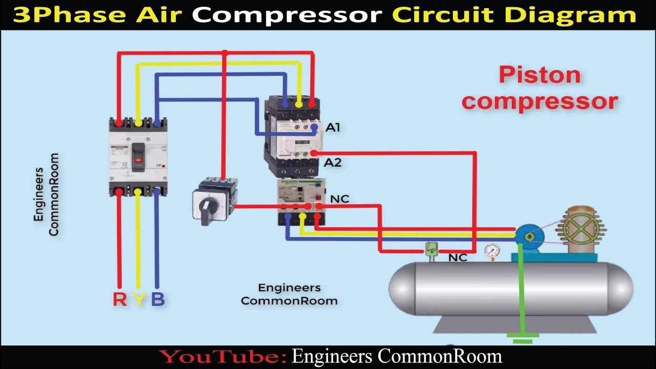
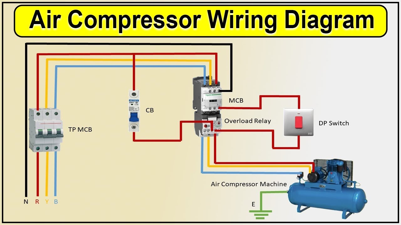
Air Compressor Circuit Diagram Engineers CommonRoom Electrical Circuit Diagram YouTube
The image title is Air Compressor Circuit Diagram Engineers CommonRoom Electrical Circuit Diagram YouTube, features dimensions of width 1280 px and height 720 px, with a file size of 1280 x 720 px. This image image/jpeg type visual are source from www.youtube.com.
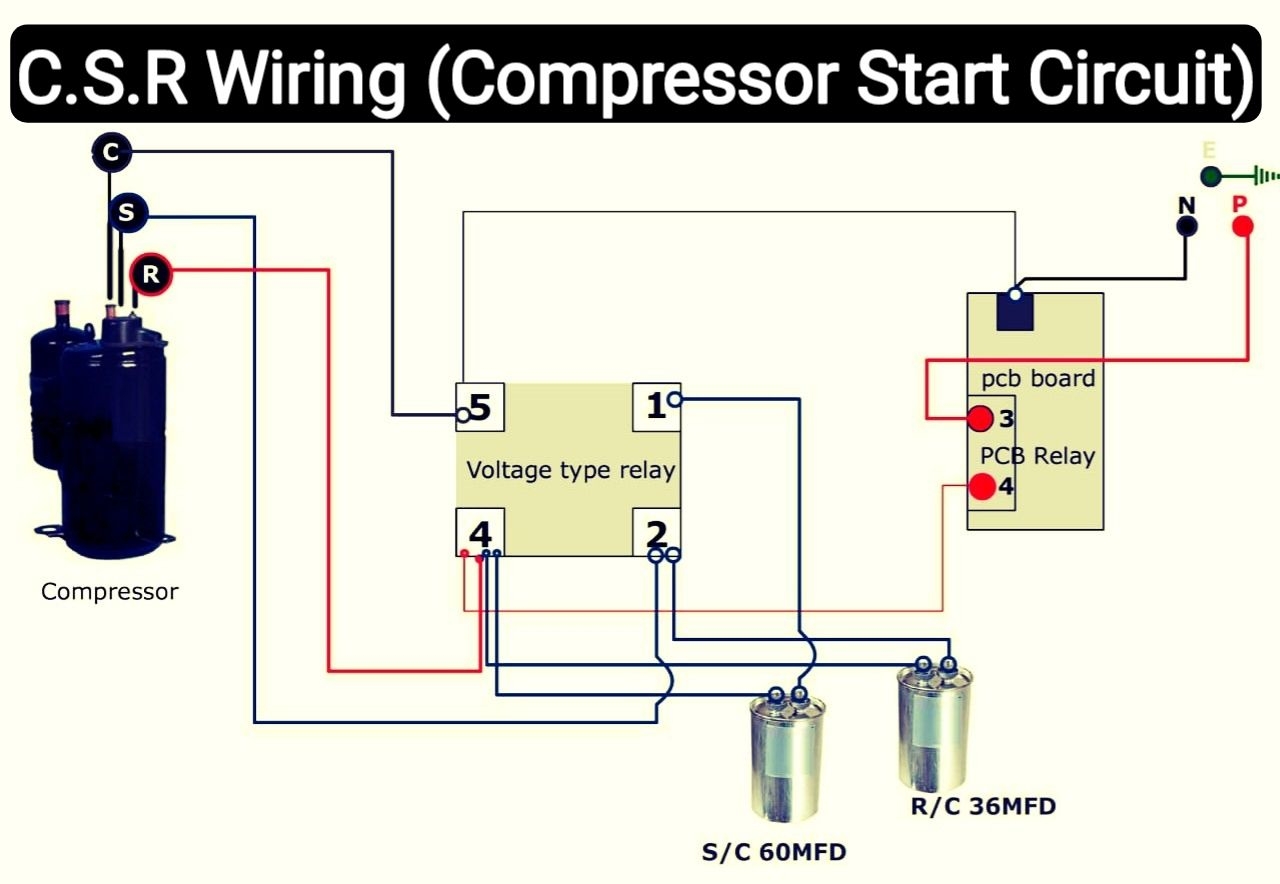
Air Conditioner C S R Wiring Diagram Compressor Start Full Wiring Fully4w Refrigeration And Air Conditioning Hvac Air Conditioning Air Conditioner Compressor
The image title is Air Conditioner C S R Wiring Diagram Compressor Start Full Wiring Fully4w Refrigeration And Air Conditioning Hvac Air Conditioning Air Conditioner Compressor, features dimensions of width 1280 px and height 884 px, with a file size of 1280 x 884 px. This image image/jpeg type visual are source from in.pinterest.com.
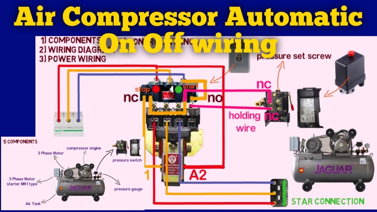
Air Compressor Automatic On Off Wiring Diagram Air Compressor YouTube
The image title is Air Compressor Automatic On Off Wiring Diagram Air Compressor YouTube, features dimensions of width 1280 px and height 720 px, with a file size of 1280 x 720. This image image/jpeg type visual are source from www.youtube.com.
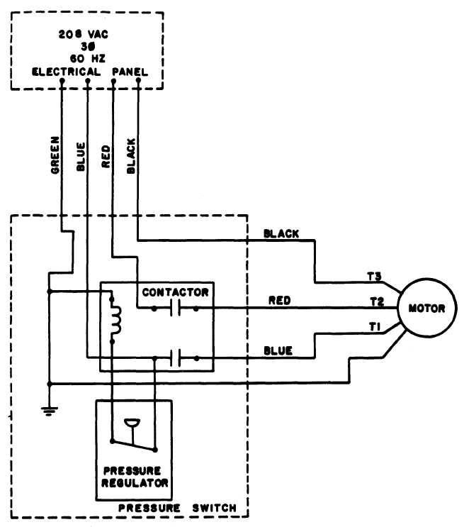
Figure 7 Air Compressor Wiring Diagram
The image title is Figure 7 Air Compressor Wiring Diagram, features dimensions of width 655 px and height 743 px, with a file size of 655 x 743. This image image/jpeg type visual are source from clothingandindividualequipment.tpub.com.
Air Compressor Wiring Diagram Air Compressor YouTube
The image title is Air Compressor Wiring Diagram Air Compressor YouTube, features dimensions of width 1280 px and height 720 px, with a file size of 1280 x 720. This image image/jpeg type visual are source from www.youtube.com
FIGURE 2 7 Air Compressor Wiring Diagram
The image title is FIGURE 2 7 Air Compressor Wiring Diagram, features dimensions of width 663 px and height 744 px, with a file size of 663 x 744. This image image/jpeg type visual are source from clothingandindividualequipment.tpub.com.
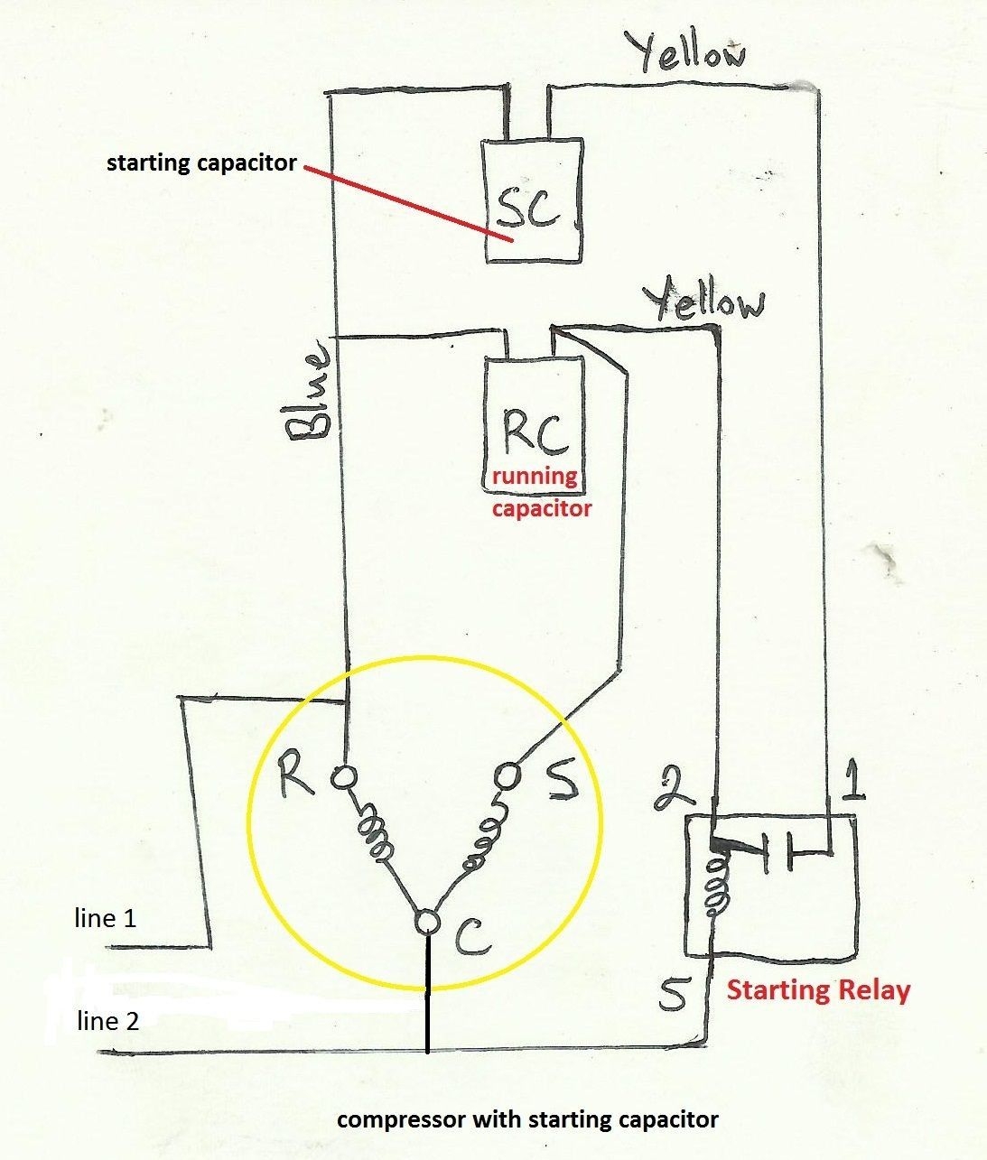
Awesome Refrigerator Compressor Relay Wiring Diagram Electrical Wiring Diagram Electrical Circuit Diagram Refrigeration And Air Conditioning
The image title is Awesome Refrigerator Compressor Relay Wiring Diagram Electrical Wiring Diagram Electrical Circuit Diagram Refrigeration And Air Conditioning, features dimensions of width 1093 px and height 1285 px, with a file size of 1093 x 1285. This image image/jpeg type visual are source from www.pinterest.com.
Capacitors For Compressor Wiring Diagram Ac Capacitor Hvac Compressor Air Compressor Motor
The image title is Capacitors For Compressor Wiring Diagram Ac Capacitor Hvac Compressor Air Compressor Motor, features dimensions of width 544 px and height 600 px, with a file size of 544 x 600.
The images on this page, sourced from Google for educational purposes, may be copyrighted. If you own an image and wish its removal or have copyright concerns, please contact us. We aim to promptly address these issues in compliance with our copyright policy and DMCA standards. Your cooperation is appreciated.
Related Keywords to Compressor Wiring Diagram:
compressor wiring diagram,compressor wiring diagram 3 phase,compressor wiring diagram ac,compressor wiring diagram pdf,compressor wiring diagram single phase
