Table of Contents
Exploring the Intricacies of Compressor Diagram Wiring
When it comes to the world of HVAC systems, one of the most critical components is the compressor. The heart of the system, the compressor plays a vital role in ensuring efficient cooling or heating within a space. However, understanding how compressors work and how they are wired can be a complex and daunting task. This is where compressor diagram wiring comes into play, offering a visual representation of the electrical connections and components involved in the compressor system. In this article, we delve into the world of compressor diagram wiring, unraveling its intricacies and shedding light on its importance in the realm of HVAC systems.
The Basics of Compressor Diagram Wiring
Compressor diagram wiring serves as a roadmap for technicians and HVAC professionals, guiding them through the intricate network of electrical connections within a compressor system. These diagrams provide a visual representation of how various components such as capacitors, relays, contactors, and terminals are interconnected to facilitate the operation of the compressor. By studying these diagrams, technicians can troubleshoot issues, identify faulty components, and ensure that the compressor system functions optimally.
The Components of a Compressor Diagram
A typical compressor diagram consists of various components that work together to regulate the flow of electricity and enable the compressor to function smoothly. Some of the key components depicted in a compressor diagram include:
- Start Capacitor
- Run Capacitor
- Relay
- Contactors
- Thermal Overload Protector
Each of these components plays a crucial role in ensuring the proper operation of the compressor, and their wiring connections are clearly illustrated in the compressor diagram for easy reference.
Understanding Wiring Codes and Symbols
In addition to depicting the various components of the compressor system, compressor diagram wiring also incorporates wiring codes and symbols to indicate the specific electrical connections between components. Understanding these codes and symbols is essential for interpreting the diagram accurately and ensuring that the wiring is done correctly. Common symbols found in compressor diagrams include:
- Lines and Dots to represent wires and connections
- Numbers to indicate wire gauge
- Colors to denote wire insulation
Troubleshooting with Compressor Diagram Wiring
One of the primary benefits of utilizing compressor diagram wiring is its utility in troubleshooting compressor issues. By referencing the diagram, technicians can trace the flow of electricity, identify faulty connections, and pinpoint the root cause of compressor malfunctions. This systematic approach to troubleshooting not only saves time but also ensures that repairs are carried out accurately and efficiently.
Conclusion
In the realm of HVAC systems, compressor diagram wiring serves as a valuable tool for technicians and professionals, offering a comprehensive visual representation of the electrical connections within a compressor system. By understanding the basics of compressor diagram wiring, decoding wiring codes and symbols, and leveraging these diagrams for troubleshooting purposes, HVAC professionals can enhance their skills and ensure the optimal performance of compressor systems. With its ability to streamline the diagnosis and repair process, compressor diagram wiring proves to be an indispensable asset in the world of HVAC maintenance and servicing.
Related to Compressor Diagram Wiring
- Color Iphone Charger Wiring Diagram
- Color Obd2 Wiring Diagram
- Color Vw Radio Wiring Diagram
- Color Wire 4 Pin Cb Mic Wiring Diagram
- Combined Brake And Turn Signal Wiring Diagram
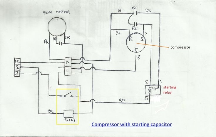
Air Conditioner Compressor Wiring Diagram Before You Call A AC Repair Man Visit My Blog Refrigeration And Air Conditioning Capacitor Air Conditioner Capacitor
The image title is Air Conditioner Compressor Wiring Diagram Before You Call A AC Repair Man Visit My Blog Refrigeration And Air Conditioning Capacitor Air Conditioner Capacitor, features dimensions of width 735 px and height 465 px, with a file size of 735 x 465 px. This image image/jpeg type visual are source from www.pinterest.com.
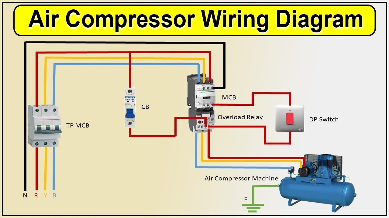
Air Compressor Wiring Diagram Air Compressor YouTube
The image title is Air Compressor Wiring Diagram Air Compressor YouTube, features dimensions of width 1280 px and height 720 px, with a file size of 1280 x 720 px. This image image/jpeg type visual are source from www.youtube.com.
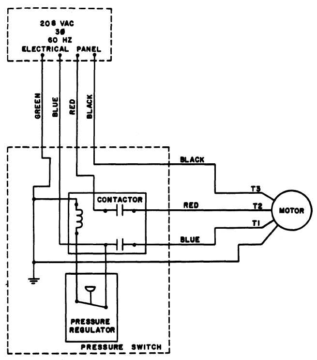
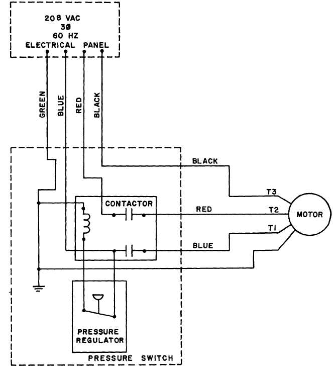
Figure 7 Air Compressor Wiring Diagram
The image title is Figure 7 Air Compressor Wiring Diagram, features dimensions of width 655 px and height 743 px, with a file size of 655 x 743. This image image/jpeg type visual are source from clothingandindividualequipment.tpub.com.
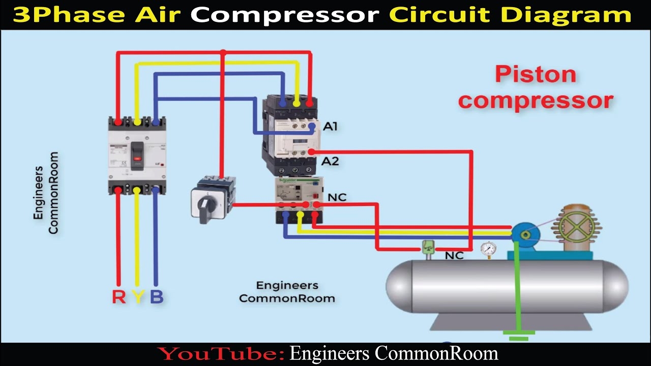
Air Compressor Circuit Diagram Engineers CommonRoom Electrical Circuit Diagram YouTube
The image title is Air Compressor Circuit Diagram Engineers CommonRoom Electrical Circuit Diagram YouTube, features dimensions of width 1280 px and height 720 px, with a file size of 1280 x 720. This image image/jpeg type visual are source from www.youtube.com.
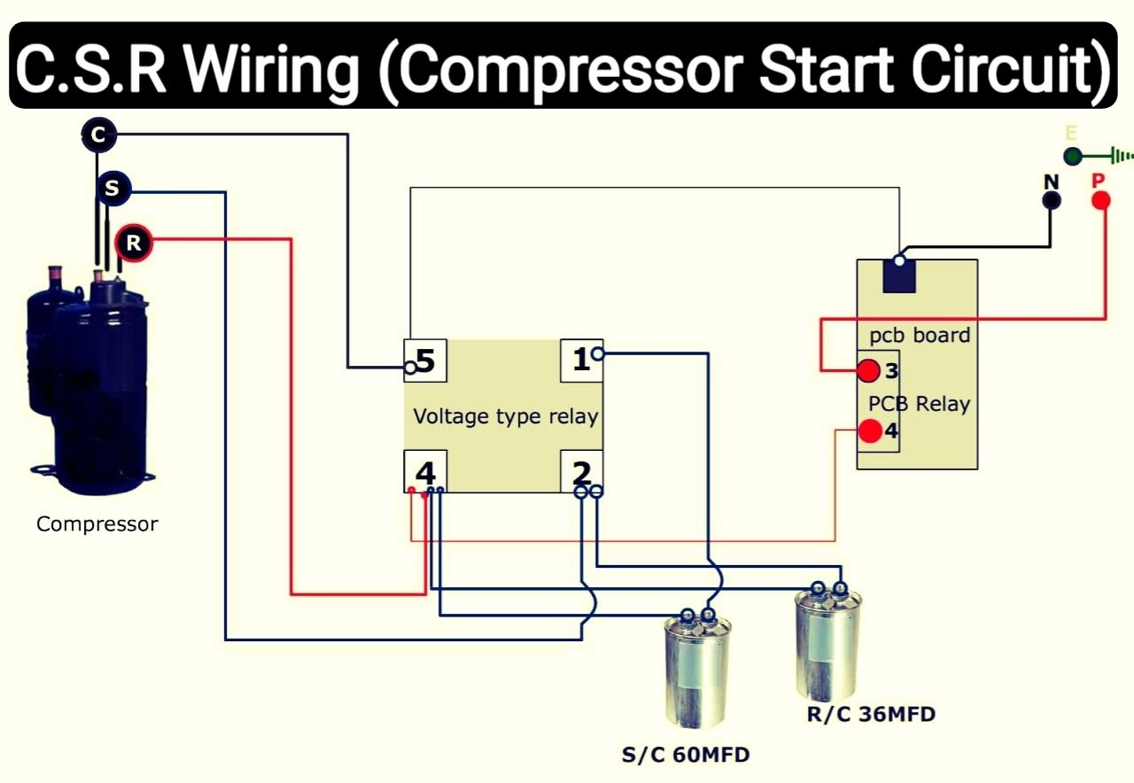
Air Conditioner C S R Wiring Diagram Compressor Start Full Wiring Fully4w Refrigeration And Air Conditioning Hvac Air Conditioning Air Conditioner Compressor
The image title is Air Conditioner C S R Wiring Diagram Compressor Start Full Wiring Fully4w Refrigeration And Air Conditioning Hvac Air Conditioning Air Conditioner Compressor, features dimensions of width 1280 px and height 884 px, with a file size of 1280 x 884. This image image/jpeg type visual are source from in.pinterest.com
FIGURE 2 7 Air Compressor Wiring Diagram
The image title is FIGURE 2 7 Air Compressor Wiring Diagram, features dimensions of width 663 px and height 744 px, with a file size of 663 x 744. This image image/jpeg type visual are source from clothingandindividualequipment.tpub.com.
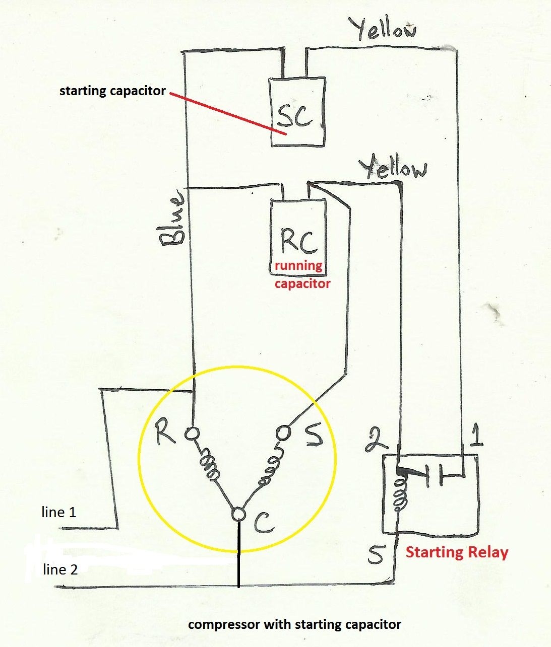
Air Compressor Capacitor Wiring Diagram Before You Call A AC Repair Man Electrical Wiring Diagram Electrical Circuit Diagram Refrigeration And Air Conditioning
The image title is Air Compressor Capacitor Wiring Diagram Before You Call A AC Repair Man Electrical Wiring Diagram Electrical Circuit Diagram Refrigeration And Air Conditioning, features dimensions of width 1093 px and height 1285 px, with a file size of 1093 x 1285. This image image/jpeg type visual are source from www.pinterest.ph.
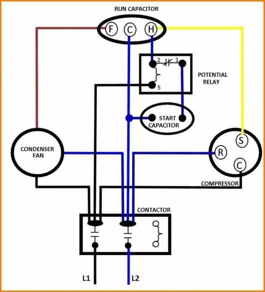
Capacitors For Compressor Wiring Diagram Ac Capacitor Hvac Compressor Air Compressor Motor
The image title is Capacitors For Compressor Wiring Diagram Ac Capacitor Hvac Compressor Air Compressor Motor, features dimensions of width 544 px and height 600 px, with a file size of 544 x 600.
The images on this page, sourced from Google for educational purposes, may be copyrighted. If you own an image and wish its removal or have copyright concerns, please contact us. We aim to promptly address these issues in compliance with our copyright policy and DMCA standards. Your cooperation is appreciated.
Related Keywords to Compressor Diagram Wiring:
compressor diagram wiring,compressor wiring diagram 3 phase,compressor wiring diagram pdf,compressor wiring diagram single phase,compressor wiring diagram with start capacitor
