Table of Contents
Exploring the Value of Compressor Wiring Diagram Single Phase
When it comes to understanding the intricate workings of electrical systems, having access to clear and detailed wiring diagrams is essential. In the realm of compressors, a single-phase compressor wiring diagram serves as a roadmap for technicians and enthusiasts alike, guiding them through the wiring connections and configurations necessary for optimal performance. This invaluable resource not only simplifies the installation process but also ensures the safety and efficiency of the compressor system. Let’s delve into the world of compressor wiring diagrams for single-phase setups and uncover the wealth of knowledge they offer.
The Basics of Single-Phase Compressor Wiring Diagrams
Before delving into the specifics of compressor wiring diagrams, it’s crucial to grasp the fundamentals of single-phase electrical systems. In a single-phase setup, power is delivered through two conductors – a phase conductor and a neutral conductor. Understanding how these components interact and the role they play in powering a compressor is essential for interpreting wiring diagrams accurately.
Key Components in a Compressor Wiring Diagram
A typical compressor wiring diagram for a single-phase system will include key components such as the power supply, start capacitor, run capacitor, motor, and various terminals and connections. Each component plays a vital role in the operation of the compressor, and the wiring diagram acts as a visual guide to ensure that these elements are correctly interconnected.
Interpreting Symbols and Notations
Compressor wiring diagrams are filled with symbols and notations that convey important information about the electrical connections and components involved. From identifying the start and run terminals to understanding the direction of current flow, interpreting these symbols is crucial for successfully wiring a compressor system.
Benefits of Using a Compressor Wiring Diagram
The value of a compressor wiring diagram for single-phase systems cannot be overstated. By providing a clear visual representation of the electrical connections and components, these diagrams offer several benefits:
- Ensuring Correct Wiring: Following a wiring diagram helps prevent errors and ensures that all connections are made accurately.
- Facilitating Troubleshooting: When issues arise, a wiring diagram serves as a reference point for diagnosing and resolving electrical problems.
- Promoting Safety: Proper wiring practices outlined in the diagram enhance safety by reducing the risk of electrical hazards.
- Improving Efficiency: A well-wired compressor system operates more efficiently, leading to optimal performance and longevity.
Guidelines for Using Compressor Wiring Diagrams
To make the most of a compressor wiring diagram for single-phase systems, it’s essential to follow some guidelines:
- Study the Diagram Carefully: Take the time to familiarize yourself with the symbols and connections depicted in the wiring diagram.
- Double-Check Connections: Before powering up the compressor, verify that all wiring connections match the diagram.
- Seek Professional Assistance: If you’re unsure about any aspect of the wiring process, don’t hesitate to consult an expert for guidance.
Conclusion
In conclusion, a compressor wiring diagram for single-phase systems is an invaluable tool that simplifies the installation, maintenance, and troubleshooting of compressor systems. By understanding the key components, interpreting symbols, and adhering to wiring guidelines, enthusiasts and technicians can harness the power of these diagrams to ensure the safe and efficient operation of their compressors. Whether you’re a seasoned professional or a DIY enthusiast, mastering the art of reading and implementing compressor wiring diagrams is a skill that can elevate your electrical expertise to new heights.
Related to Compressor Wiring Diagram Single Phase
- Color Wire 4 Pin Cb Mic Wiring Diagram
- Combined Brake And Turn Signal Wiring Diagram
- Compressor Diagram Wiring
- Compressor Start Relay Wiring Diagram
- Compressor Wiring Diagram
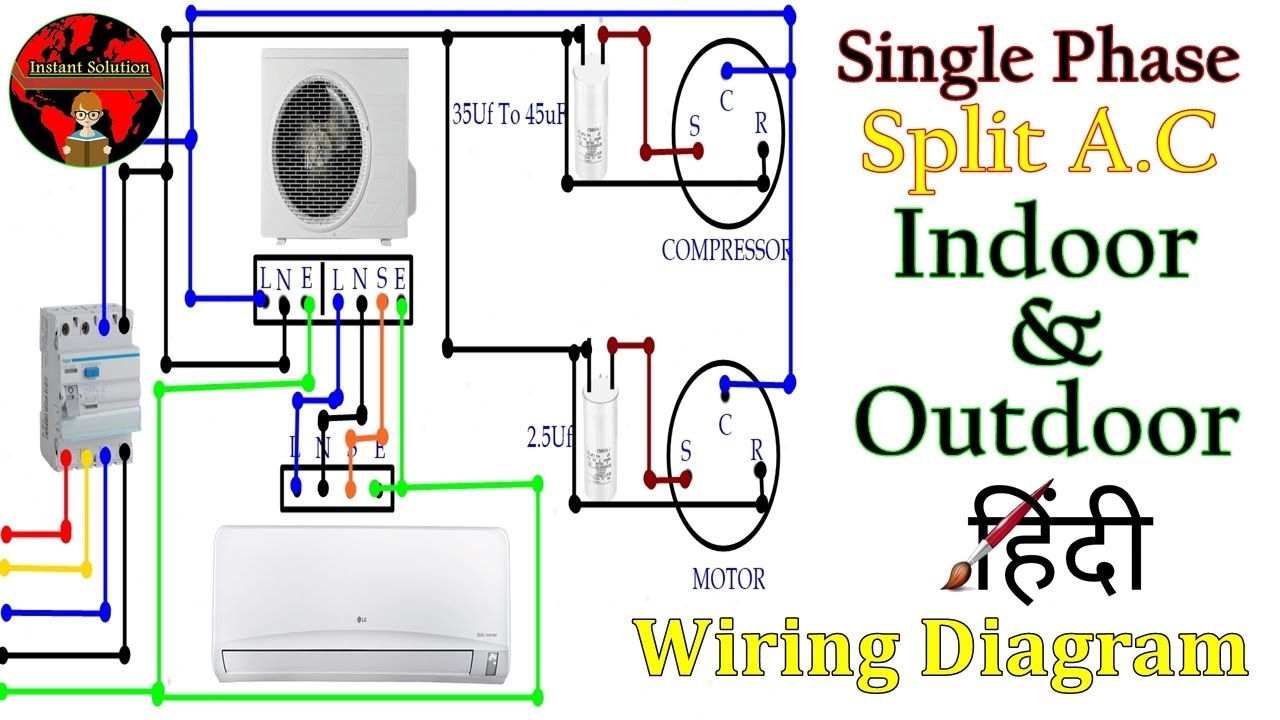
220 Volt Single Phase Split AC Compressor Motor Wiring Diagram In Hindi YouTube
The image title is 220 Volt Single Phase Split AC Compressor Motor Wiring Diagram In Hindi YouTube, features dimensions of width 1280 px and height 720 px, with a file size of 1280 x 720 px. This image image/jpeg type visual are source from m.youtube.com.
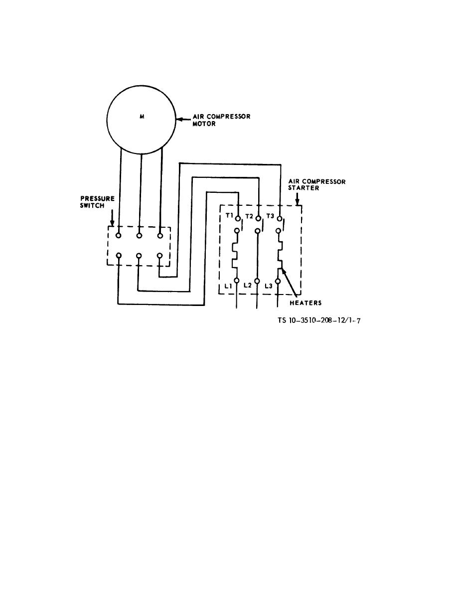
Figure 1 7 Air Compressor Wiring Diagram
The image title is Figure 1 7 Air Compressor Wiring Diagram, features dimensions of width 915 px and height 1188 px, with a file size of 915 x 1188 px. This image image/jpeg type visual are source from clothingandindividualequipment.tpub.com.
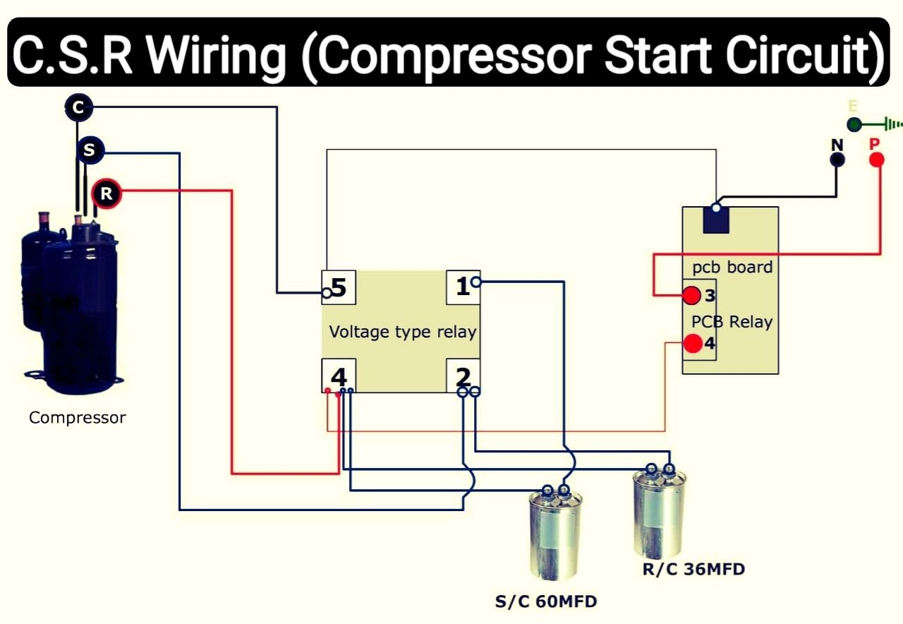
Air Conditioner C S R Wiring Diagram Compressor Start Full Wiring Fully4w Refrigeration And Air Conditioning Hvac Air Conditioning Air Conditioner Compressor
The image title is Air Conditioner C S R Wiring Diagram Compressor Start Full Wiring Fully4w Refrigeration And Air Conditioning Hvac Air Conditioning Air Conditioner Compressor, features dimensions of width 1280 px and height 884 px, with a file size of 1280 x 884. This image image/jpeg type visual are source from in.pinterest.com.
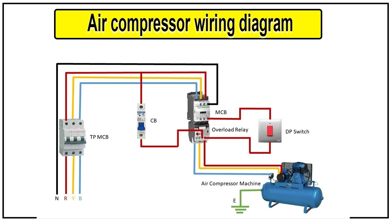
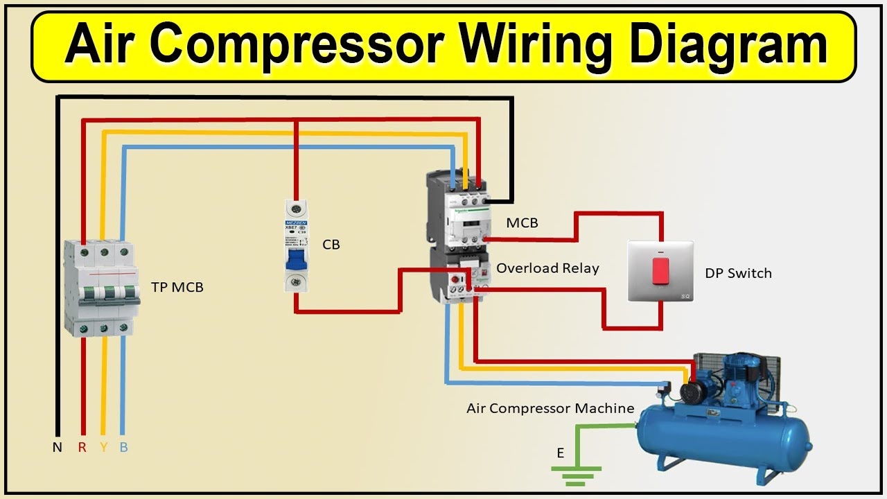
Air Compressor Wiring Diagram Air Compressor Compressor YouTube
The image title is Air Compressor Wiring Diagram Air Compressor Compressor YouTube, features dimensions of width 1280 px and height 720 px, with a file size of 1280 x 720. This image image/jpeg type visual are source from www.youtube.com.
Air Compressor Wiring Diagram Air Compressor YouTube
The image title is Air Compressor Wiring Diagram Air Compressor YouTube, features dimensions of width 1280 px and height 720 px, with a file size of 1280 x 720. This image image/jpeg type visual are source from www.youtube.com
Awesome Refrigerator Compressor Relay Wiring Diagram Electrical Wiring Diagram Electrical Circuit Diagram Refrigeration And Air Conditioning
The image title is Awesome Refrigerator Compressor Relay Wiring Diagram Electrical Wiring Diagram Electrical Circuit Diagram Refrigeration And Air Conditioning, features dimensions of width 1093 px and height 1285 px, with a file size of 1093 x 1285. This image image/jpeg type visual are source from www.pinterest.com.
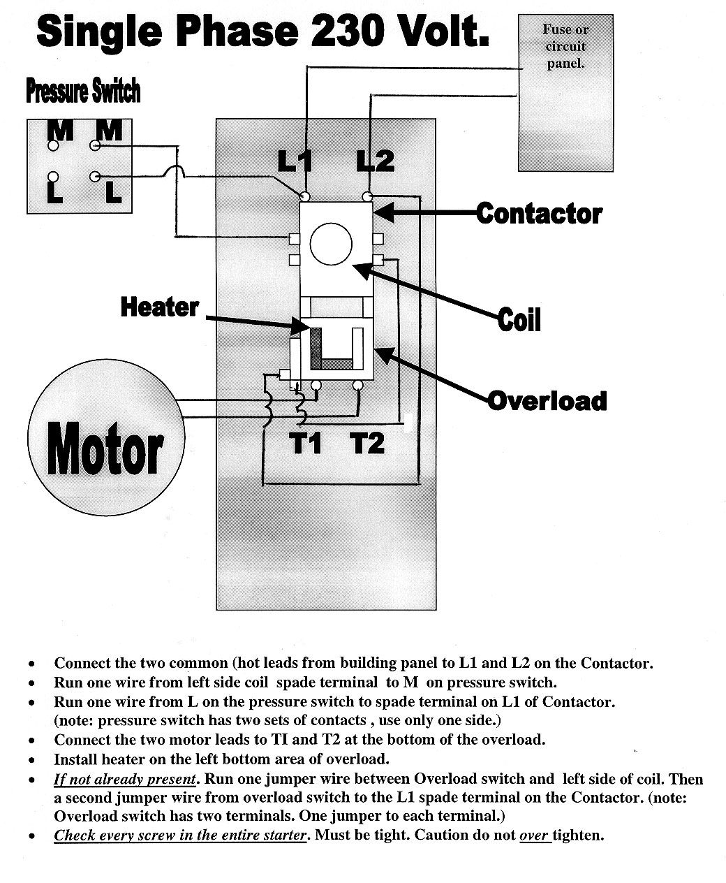
70 Lovely Single Phase Magnetic Starter Wiring Diagram Air Compressor Pressure Switch Electrical Wiring Diagram Electrical Circuit Diagram
The image title is 70 Lovely Single Phase Magnetic Starter Wiring Diagram Air Compressor Pressure Switch Electrical Wiring Diagram Electrical Circuit Diagram, features dimensions of width 1040 px and height 1264 px, with a file size of 1040 x 1264. This image image/jpeg type visual are source from www.pinterest.com.
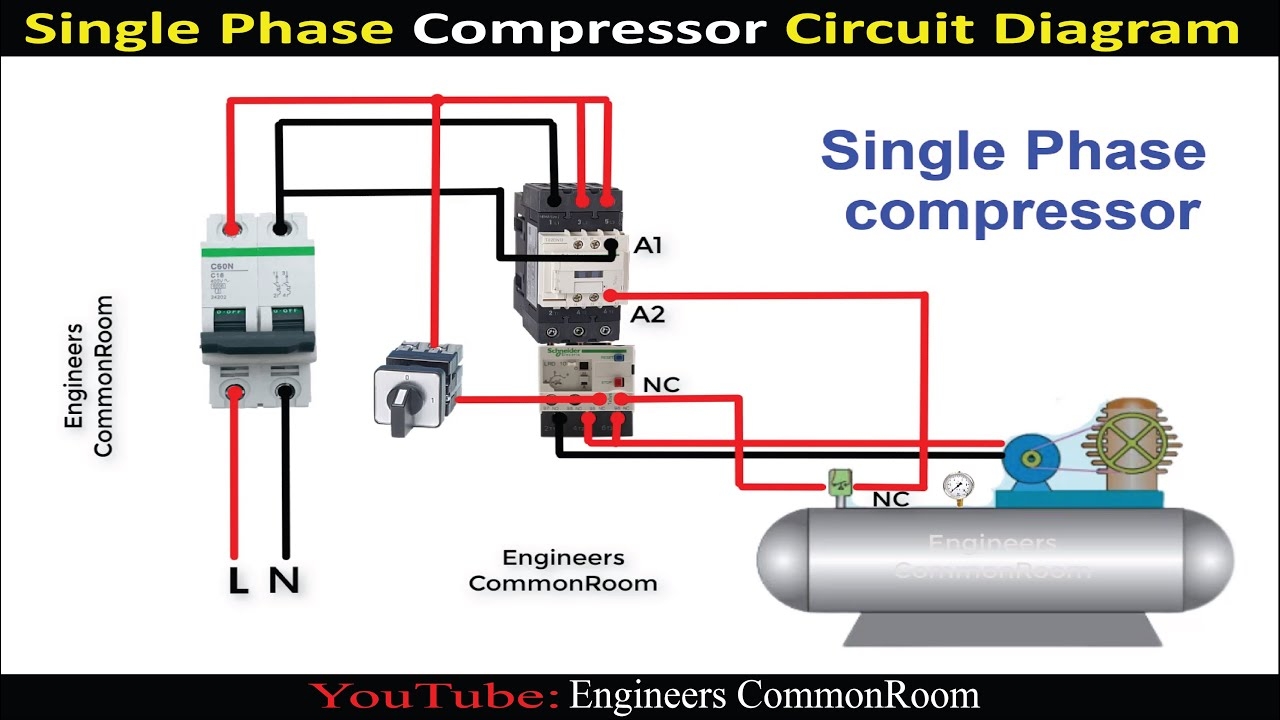
Single Phase Compressor Engineers CommonRoom Electrical Circuit Diagram YouTube
The image title is Single Phase Compressor Engineers CommonRoom Electrical Circuit Diagram YouTube, features dimensions of width 1280 px and height 720 px, with a file size of 1280 x 720.
The images on this page, sourced from Google for educational purposes, may be copyrighted. If you own an image and wish its removal or have copyright concerns, please contact us. We aim to promptly address these issues in compliance with our copyright policy and DMCA standards. Your cooperation is appreciated.
Related Keywords to Compressor Wiring Diagram Single Phase:
ac compressor wiring diagram single phase,air compressor wiring diagram single phase,capacitor compressor wiring diagram single phase,compressor wiring diagram single phase,copeland compressor wiring diagram single phase
