Table of Contents
The Ultimate Guide to Contact Wiring Diagrams
The Ultimate Guide to Contact Wiring Diagrams
When it comes to electrical systems, having a comprehensive understanding of contact wiring diagrams is essential. These diagrams provide a visual representation of how contacts interact within a circuit, offering valuable insights into the operation and functionality of various electrical components. Whether you are a seasoned electrician or a DIY enthusiast looking to troubleshoot electrical issues, contact wiring diagrams are indispensable tools that can help you navigate complex circuits with ease.
The Basics of Contact Wiring Diagrams
Contact wiring diagrams depict the connections between electrical contacts, switches, relays, and other components within a circuit. By illustrating the flow of current and the relationships between different elements, these diagrams enable users to visualize the circuit’s operation and identify potential issues. Understanding the symbols and conventions used in contact wiring diagrams is crucial for interpreting these diagrams accurately and effectively.
Key Components of Contact Wiring Diagrams
Contact wiring diagrams typically include symbols such as open contacts, closed contacts, coil symbols, and connection points. Open contacts indicate that a circuit is open and the current cannot flow, while closed contacts signify a closed circuit where current can pass through. Coil symbols represent electromagnetic coils used in relays and contactors, while connection points show where different components are connected within the circuit.
Interpreting Contact Wiring Diagrams
To interpret a contact wiring diagram accurately, it is essential to understand the logic of the circuit and how different components interact with each other. By following the flow of current through the diagram and tracing the connections between contacts, switches, and relays, users can troubleshoot issues, identify faulty components, and optimize the performance of the electrical system.
Benefits of Using Contact Wiring Diagrams
Contact wiring diagrams offer numerous benefits for electricians, engineers, and DIY enthusiasts alike. These diagrams provide a clear visual representation of complex circuits, making it easier to understand the circuit’s operation, diagnose problems, and plan modifications or upgrades. By referencing contact wiring diagrams, users can work more efficiently, reduce errors, and ensure the safety and reliability of electrical systems.
Enhancing Safety and Efficiency
By following contact wiring diagrams, users can ensure that electrical connections are made correctly and that circuits are configured in a safe and efficient manner. This reduces the risk of electrical faults, short circuits, and other hazards, enhancing the overall safety of the system. Additionally, by understanding the layout of the circuit and the function of each component, users can troubleshoot issues more effectively and minimize downtime.
Optimizing Performance and Functionality
Contact wiring diagrams also play a crucial role in optimizing the performance and functionality of electrical systems. By analyzing the interactions between contacts, switches, and relays, users can identify opportunities for improving efficiency, reducing energy consumption, and enhancing the overall functionality of the circuit. This insight enables users to make informed decisions about upgrades, modifications, and maintenance tasks.
Conclusion
In conclusion, contact wiring diagrams are invaluable tools for anyone working with electrical systems. By providing a clear visual representation of circuits, these diagrams enable users to understand the operation of electrical components, diagnose issues, and optimize performance. Whether you are a professional electrician or a DIY enthusiast, mastering the art of interpreting contact wiring diagrams can elevate your skills and empower you to tackle complex electrical projects with confidence.
Related to Contact Wiring Diagram
- Computer Power Supply Wiring Diagram
- Condensate Pump Wiring Diagram
- Condenser Wiring Diagram
- Connection 3 Speed Fan Motor Wiring Diagram
- Connection Single Phase Motor Wiring Diagram Forward Reverse
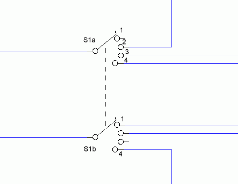
Switch Wiring And Relay Contacts Alarms Security Related Schematics And Tutorials Electronics Hobby Projects
The image title is Switch Wiring And Relay Contacts Alarms Security Related Schematics And Tutorials Electronics Hobby Projects, features dimensions of width 483 px and height 373 px, with a file size of 483 x 373 px. This image image/gif type visual are source from www.hobbyprojects.com.
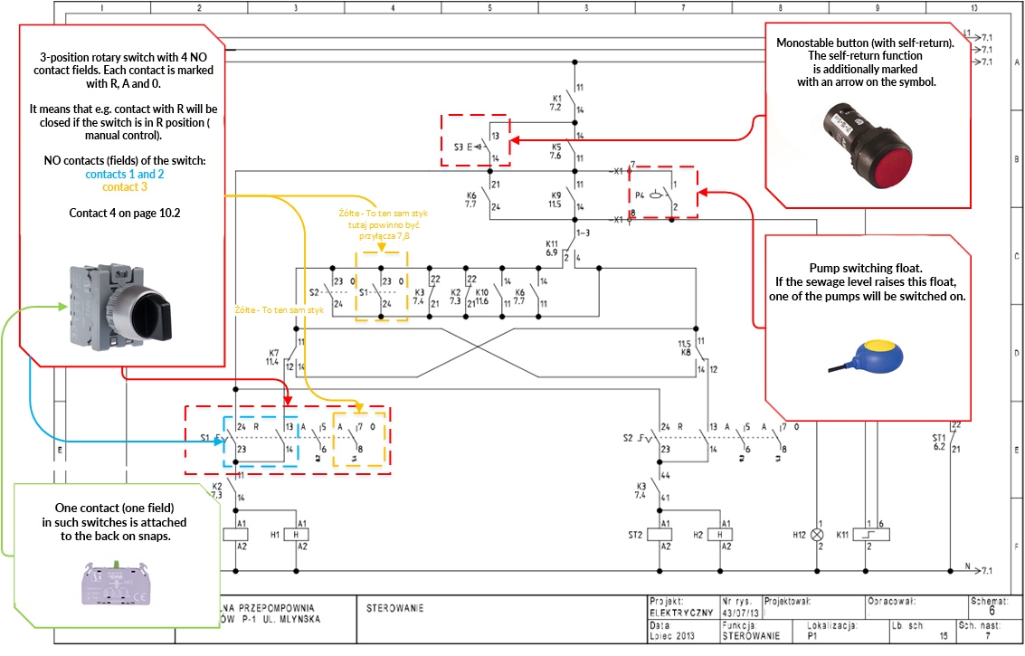
Electrical Symbols How To Read Schematics 4 CONTACTS BUTTONS SENSORS Blog Related To Industrial Automation PLC HMI Control Systems
The image title is Electrical Symbols How To Read Schematics 4 CONTACTS BUTTONS SENSORS Blog Related To Industrial Automation PLC HMI Control Systems, features dimensions of width 1133 px and height 725 px, with a file size of 1133 x 725 px. This image image/jpeg type visual are source from automationtop.com.
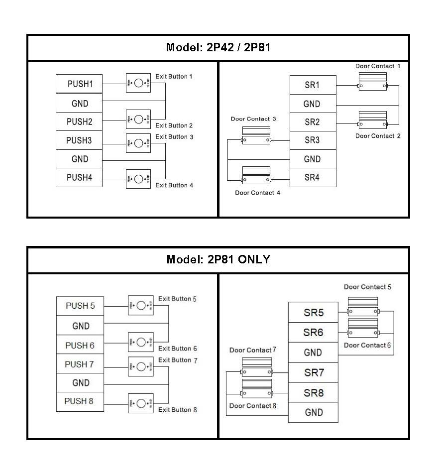
Door Contact And Exit Button Wiring Diagram Cornick
The image title is Door Contact And Exit Button Wiring Diagram Cornick, features dimensions of width 876 px and height 946 px, with a file size of 876 x 946. This image image/jpeg type visual are source from help.c5k.info.
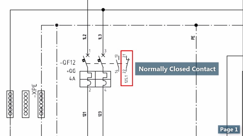
Wiring Diagrams Explained How To Read Wiring Diagrams Upmation
The image title is Wiring Diagrams Explained How To Read Wiring Diagrams Upmation, features dimensions of width 795 px and height 447 px, with a file size of 795 x 447. This image image/jpeg type visual are source from upmation.com.
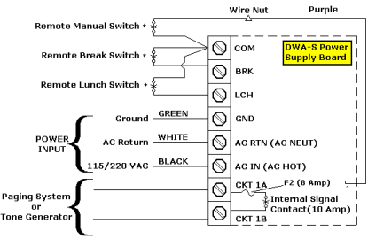
Dry Contact Closure Wiring Diagram For A DWA S Sonachron Program Timer Lathem Time
The image title is Dry Contact Closure Wiring Diagram For A DWA S Sonachron Program Timer Lathem Time, features dimensions of width 415 px and height 270 px, with a file size of 415 x 270. This image image/png type visual are source from kb.lathem.com
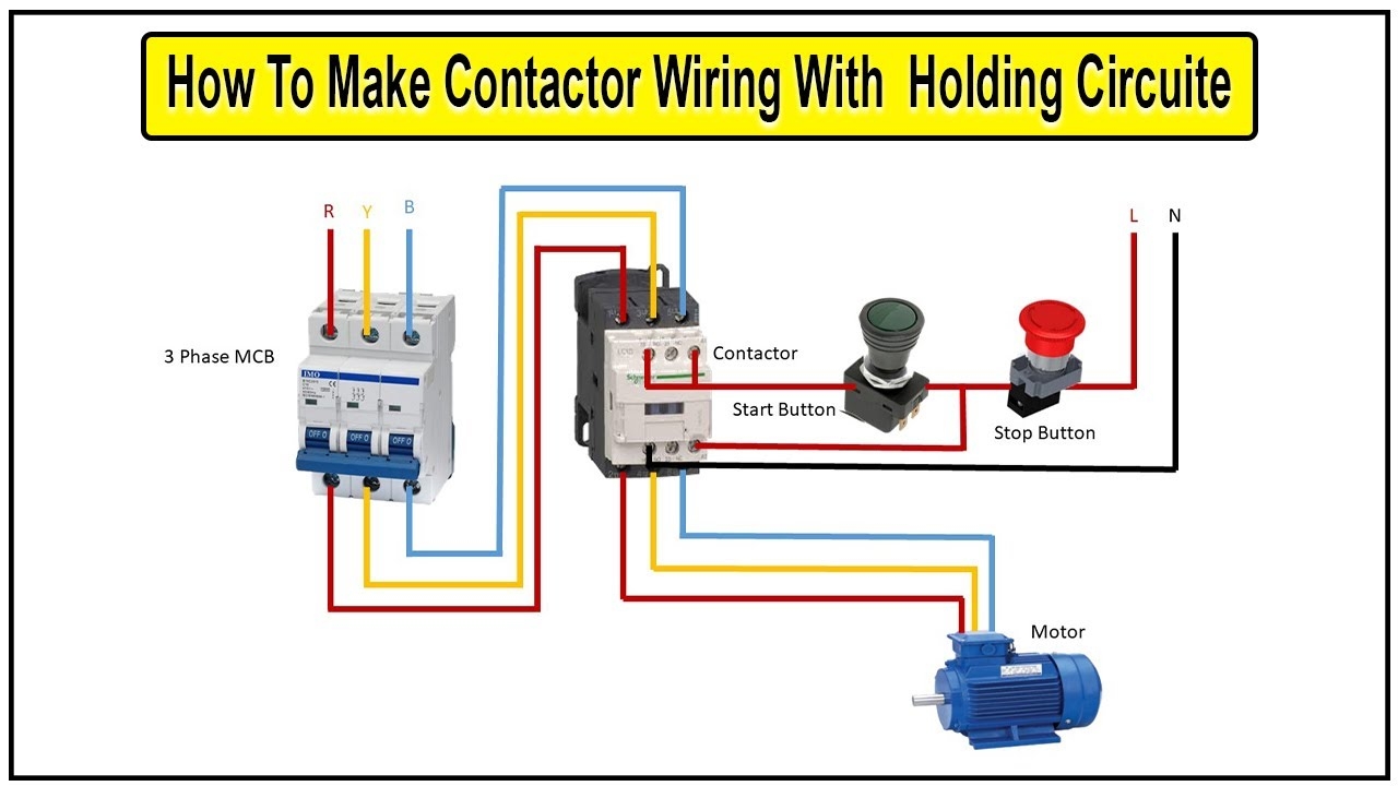
How To Make Contactor Wiring With Holding Circuit Diagram Contactor YouTube
The image title is How To Make Contactor Wiring With Holding Circuit Diagram Contactor YouTube, features dimensions of width 1280 px and height 720 px, with a file size of 1280 x 720. This image image/jpeg type visual are source from www.youtube.com.
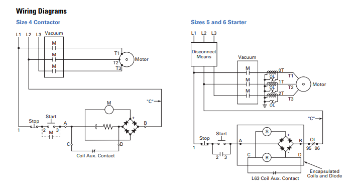
High Voltage Vacuum Contactor Wiring Diagrams Electrical Engineering Stack Exchange
The image title is High Voltage Vacuum Contactor Wiring Diagrams Electrical Engineering Stack Exchange, features dimensions of width 703 px and height 376 px, with a file size of 703 x 376. This image image/png type visual are source from electronics.stackexchange.com.
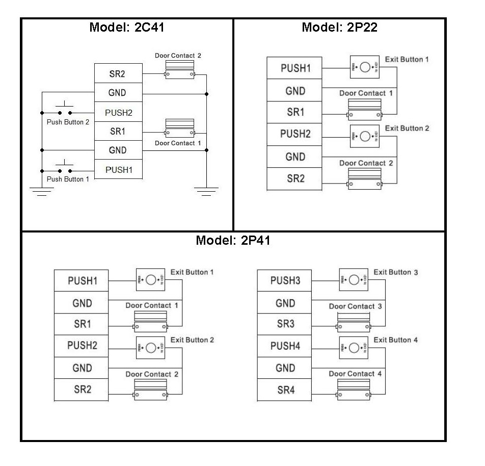
Door Contact And Exit Button Wiring Diagram Cornick
The image title is Door Contact And Exit Button Wiring Diagram Cornick, features dimensions of width 952 px and height 914 px, with a file size of 952 x 914.
The images on this page, sourced from Google for educational purposes, may be copyrighted. If you own an image and wish its removal or have copyright concerns, please contact us. We aim to promptly address these issues in compliance with our copyright policy and DMCA standards. Your cooperation is appreciated.
Related Keywords to Contact Wiring Diagram:
auxiliary contact wiring diagram,call wiring diagram,contact wiring diagram,door contact wiring diagram,dry contact wiring diagram
