Table of Contents
The Value of Understanding 3 Wire Crank Sensor Wiring Diagram
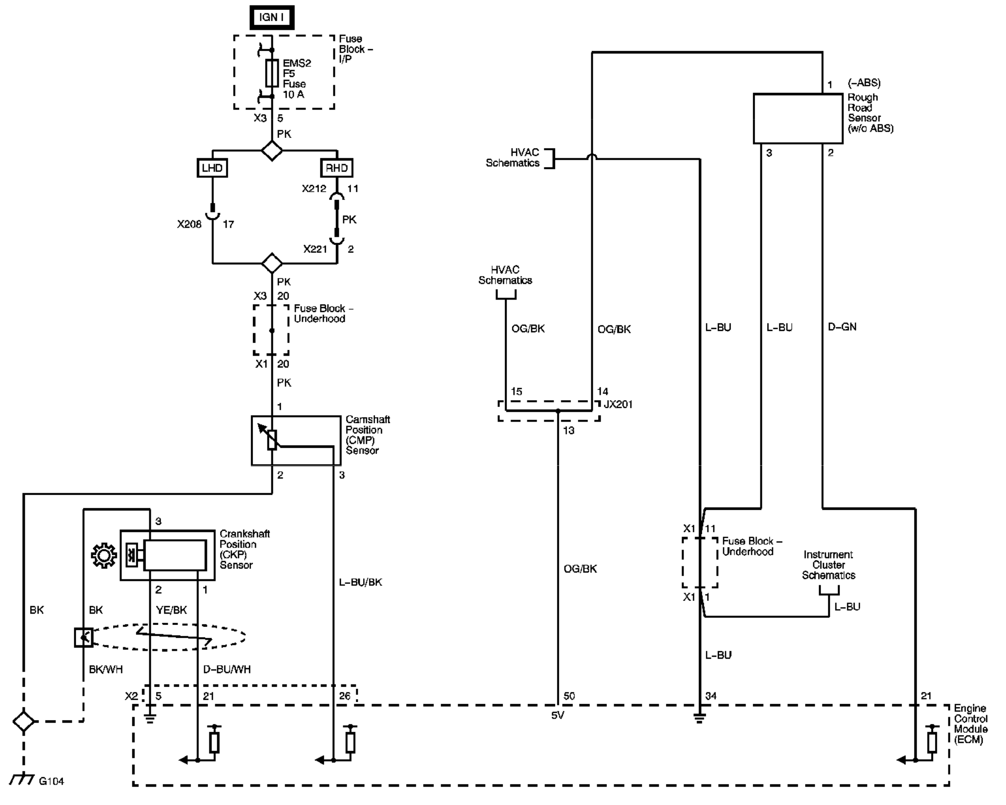
In the realm of automotive diagnostics and repair, the 3 wire crank sensor plays a crucial role in the proper functioning of a vehicle’s engine. Understanding the intricacies of the wiring diagram associated with this component is essential for any mechanic or enthusiast looking to delve into the heart of engine performance. By unraveling the mysteries of the 3 wire crank sensor wiring diagram, one can unlock a wealth of knowledge that can aid in diagnosing issues, optimizing engine performance, and ensuring smooth operation of the vehicle.
Decoding the Components of the Wiring Diagram
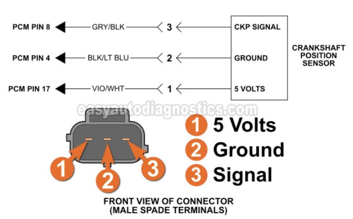
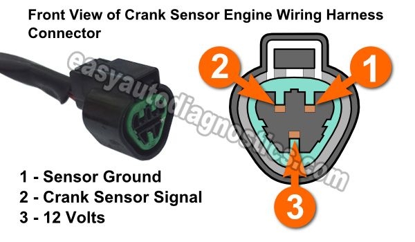
The 3 wire crank sensor wiring diagram typically consists of three primary components: power supply, ground connection, and signal output. Each wire serves a specific function in the overall operation of the sensor, with the power supply providing the necessary voltage, the ground connection ensuring proper circuit completion, and the signal output transmitting crucial data to the engine control unit. By understanding the role of each wire in the system, technicians can troubleshoot issues effectively and make informed decisions regarding repairs and maintenance.
Power Supply Wire
The power supply wire in the 3 wire crank sensor wiring diagram is responsible for delivering voltage to the sensor, enabling it to function properly. This wire is typically connected to a 12-volt power source within the vehicle’s electrical system, providing the necessary energy to power the sensor and facilitate its operation. Ensuring a stable and consistent power supply is essential for the sensor to generate accurate signals and relay vital information to the engine control unit.
Ground Connection Wire
The ground connection wire serves as the return path for electrical current within the sensor circuit, completing the circuit and ensuring proper functioning of the sensor. This wire is typically connected to the vehicle’s chassis or engine block, providing a stable ground connection that allows for the flow of electricity without interference. A solid ground connection is essential for preventing signal distortion, maintaining accuracy, and avoiding electrical issues that could impact sensor performance.
Signal Output Wire
The signal output wire in the 3 wire crank sensor wiring diagram is responsible for transmitting data from the sensor to the engine control unit, allowing for real-time monitoring of engine performance and vital parameters. This wire carries the sensor’s output signal, which contains critical information such as engine speed, position, and timing. By analyzing the signals generated by this wire, technicians can diagnose engine issues, optimize performance, and ensure smooth operation of the vehicle.
Conclusion
In conclusion, delving into the intricacies of the 3 wire crank sensor wiring diagram can provide valuable insights into the functioning of a vehicle’s engine and aid in diagnosing and resolving issues effectively. By understanding the role of each wire in the system and how they interact with one another, technicians can troubleshoot problems with precision, optimize engine performance, and ensure the efficient operation of the vehicle. Embracing the complexities of the wiring diagram can empower individuals to become more proficient in automotive diagnostics and repair, leading to enhanced vehicle performance and reliability.
Related to 3 Wire Crank Sensor Wiring Diagram
- 3 Wire Brake Light Turn Signal Wiring Diagram
- 3 Wire Brushless Motor Wiring Diagram
- 3 Wire Ceiling Fan Wiring Diagram
- 3 Wire Condenser Fan Motor Wiring Diagram
- 3 Wire Crank Position Sensor Wiring Diagram
How To Test 3 Wire Crank Sensor With Multimeter 4 Steps
The image title is How To Test 3 Wire Crank Sensor With Multimeter 4 Steps, features dimensions of width 1280 px and height 720 px, with a file size of 1280 x 720 px. This image image/jpeg type visual are source from multimetertools.com.
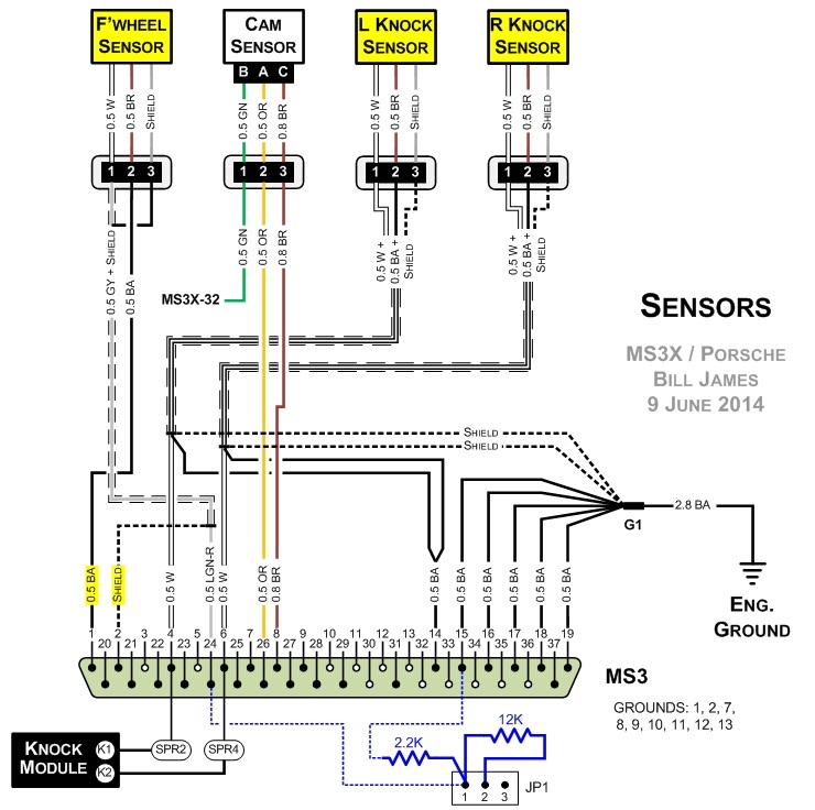
MS3X Sync Loss Problems Page 4 Pelican Parts Forums
The image title is MS3X Sync Loss Problems Page 4 Pelican Parts Forums, features dimensions of width 740 px and height 736 px, with a file size of 740 x 736 px. This image image/jpeg type visual are source from forums.pelicanparts.com.
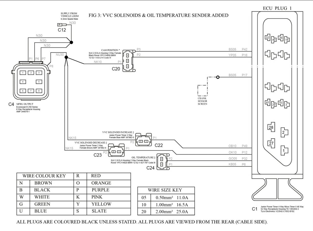
Adding VVC To An EU3 K Series Engine Wiring Loom
The image title is Adding VVC To An EU3 K Series Engine Wiring Loom, features dimensions of width 1282 px and height 946 px, with a file size of 1282 x 946. This image image/jpeg type visual are source from andrewrevill.co.uk.
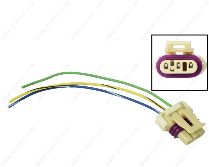
LS Gen 3 White 3 Wire CKP Crankshaft Position Sensor Connector Plug Pigtail WPCKP30 ICT Billet
The image title is LS Gen 3 White 3 Wire CKP Crankshaft Position Sensor Connector Plug Pigtail WPCKP30 ICT Billet, features dimensions of width 700 px and height 560 px, with a file size of 700 x 560. This image image/jpeg type visual are source from www.ictbillet.com.
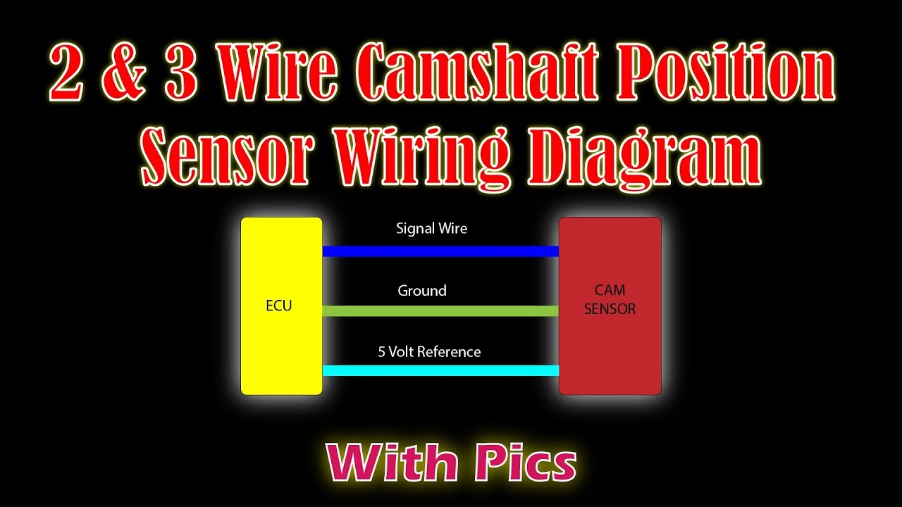
2 3 Wire Camshaft Position Wiring Diagram Easy Car Electrics YouTube
The image title is 2 3 Wire Camshaft Position Wiring Diagram Easy Car Electrics YouTube, features dimensions of width 1280 px and height 720 px, with a file size of 1280 x 720. This image image/jpeg type visual are source from www.youtube.com
Automotive How To Wire Up Camshaft Position Sensor In Lab Environment Electrical Engineering Stack Exchange
The image title is Automotive How To Wire Up Camshaft Position Sensor In Lab Environment Electrical Engineering Stack Exchange, features dimensions of width 2028 px and height 1623 px, with a file size of 2028 x 1623. This image image/png type visual are source from electronics.stackexchange.com.
Wiring Advice Focus 1 6 TDCI 2011 Crankshaft Sensor Ford Focus Club Ford Owners Club Ford Forums
The image title is Wiring Advice Focus 1 6 TDCI 2011 Crankshaft Sensor Ford Focus Club Ford Owners Club Ford Forums, features dimensions of width 1232 px and height 765 px, with a file size of 1232 x 765. This image image/jpeg type visual are source from www.fordownersclub.com.
How To Test The Crankshaft Position Sensor 1994 2004 3 0L V6 Mitsubishi Montero Map Sensor Car Mechanic Automotive Mechanic
The image title is How To Test The Crankshaft Position Sensor 1994 2004 3 0L V6 Mitsubishi Montero Map Sensor Car Mechanic Automotive Mechanic, features dimensions of width 600 px and height 350 px, with a file size of 600 x 350.
The images on this page, sourced from Google for educational purposes, may be copyrighted. If you own an image and wish its removal or have copyright concerns, please contact us. We aim to promptly address these issues in compliance with our copyright policy and DMCA standards. Your cooperation is appreciated.
Related Keywords to 3 Wire Crank Sensor Wiring Diagram:
3 wire crank position sensor wiring diagram,3 wire crank sensor wiring diagram,3-wire camshaft sensor wiring diagram,gm 3-wire crank sensor wiring diagram,vw 3-wire crank sensor wiring diagram

