Table of Contents
3 Wire Brushless Motor Wiring Diagram
Unlocking the Power of 3 Wire Brushless Motor Wiring Diagram
When it comes to harnessing the full potential of a brushless motor, understanding the intricacies of its wiring diagram is paramount. The 3 wire brushless motor wiring diagram serves as a blueprint for unlocking the efficiency and performance of these powerful motors. By delving into this diagram, you can unravel the mysteries behind how these motors operate and how to maximize their capabilities. Let’s embark on a journey to explore the inner workings of 3 wire brushless motor wiring diagrams and discover the key insights they offer.
The Basics of 3 Wire Brushless Motor Wiring
At the core of every 3 wire brushless motor is a sophisticated wiring system that enables precise control and efficient operation. Understanding the basics of this wiring is essential for anyone looking to optimize their motor performance. The 3 wire configuration consists of three main wires: the power wire, ground wire, and signal wire. Each wire plays a crucial role in ensuring the motor functions smoothly and reliably.
Power Wire
The power wire supplies the necessary voltage to drive the motor and initiate its rotation. This wire is typically connected to a power source such as a battery or power supply. Ensuring proper connection of the power wire is essential for providing the motor with the energy it needs to operate efficiently.
Ground Wire
The ground wire serves as the return path for the electrical current flowing through the motor. By grounding the motor, this wire ensures the safe dissipation of excess electrical charge and helps prevent electrical malfunctions. Proper grounding is vital for maintaining the stability and safety of the motor.
Signal Wire
The signal wire carries control signals from an external source, such as a motor controller or microcontroller, to regulate the speed and direction of the motor. By modulating the signals sent through the signal wire, operators can fine-tune the motor’s performance and achieve precise control over its operation.
Key Components of a 3 Wire Brushless Motor Wiring Diagram
A comprehensive 3 wire brushless motor wiring diagram typically includes several key components that outline the connections and functions of each wire. These components elucidate the intricate relationships between the power, ground, and signal wires, providing a roadmap for configuring and troubleshooting the motor wiring system.
Phase Wires: These wires determine the rotational direction of the motor and are crucial for synchronization.
Hall Effect Sensors: These sensors detect the position of the rotor and enable precise control over the motor.
Motor Controller: This device regulates the electrical signals sent to the motor, ensuring smooth operation and optimal performance.
Benefits of Understanding 3 Wire Brushless Motor Wiring Diagrams
By grasping the intricacies of 3 wire brushless motor wiring diagrams, enthusiasts and professionals alike can unlock a host of benefits that enhance motor efficiency and performance. Some of the key advantages of understanding these diagrams include:
Improved Troubleshooting: Knowing how to interpret wiring diagrams enables quick identification and resolution of motor issues.
Enhanced Performance Tuning: Fine-tuning the motor’s wiring based on the diagram can optimize its speed, torque, and efficiency.
Customization Capabilities: Understanding the wiring diagram empowers users to customize their motor setup for specific applications and requirements.
Conclusion
In conclusion, the 3 wire brushless motor wiring diagram is a treasure trove of insights that can revolutionize the way you harness the power of brushless motors. By immersing yourself in the intricacies of these diagrams, you can elevate your motor’s performance, troubleshoot issues with ease, and unleash a new realm of customization possibilities. Embrace the knowledge embedded in these diagrams, and embark on a journey of motor optimization and innovation like never before.
Related to 3 Wire Brushless Motor Wiring Diagram
- 3 Wire Alternator Wiring Diagram
- 3 Wire Alternator Wiring Diagram Ford
- 3 Wire Aux Cable Wiring Diagram
- 3 Wire Bilge Pump Wiring Diagram
- 3 Wire Brake Light Turn Signal Wiring Diagram
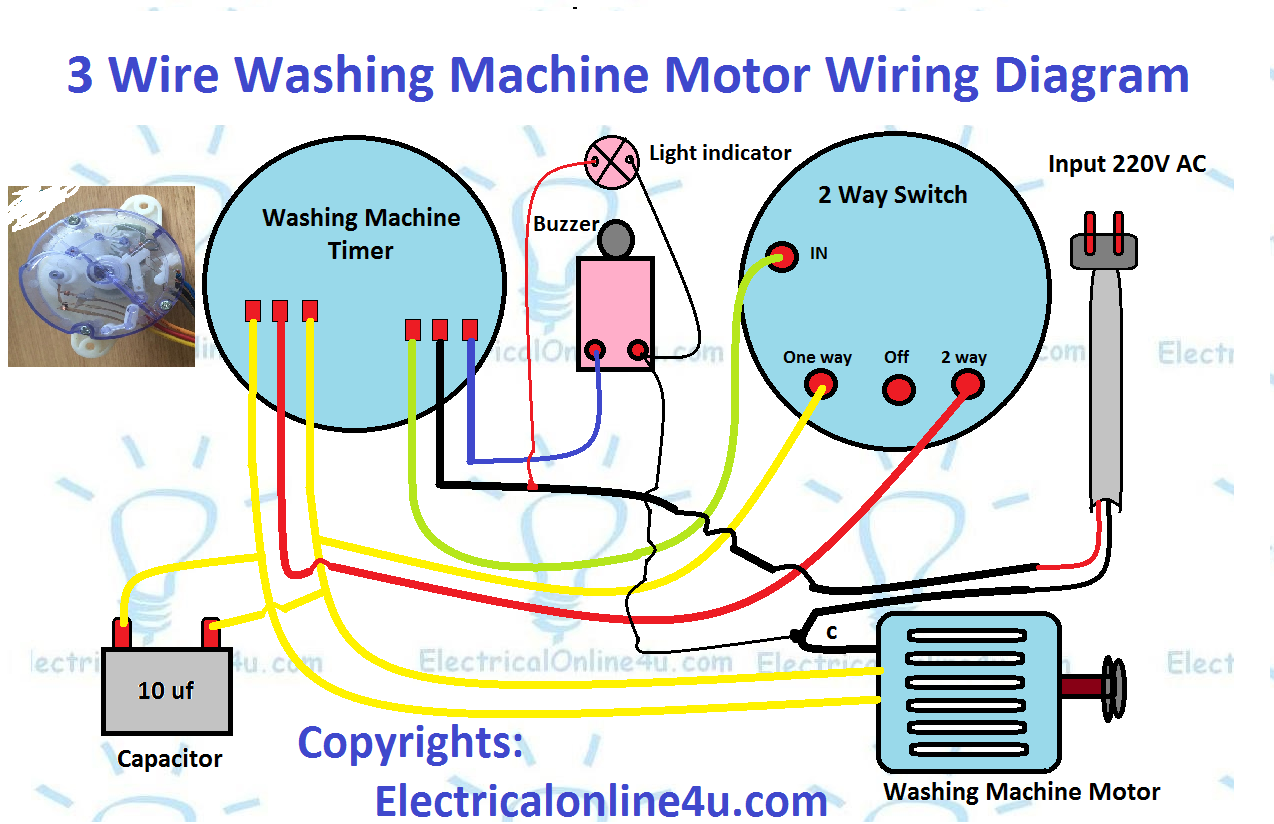
3 Wire Washing Machine Motor Wiring Diagram AKS INFO GROUP
The image title is 3 Wire Washing Machine Motor Wiring Diagram AKS INFO GROUP, features dimensions of width 1274 px and height 824 px, with a file size of 1274 x 824 px. This image image/png type visual are source from aksinfogroup.wordpress.com.
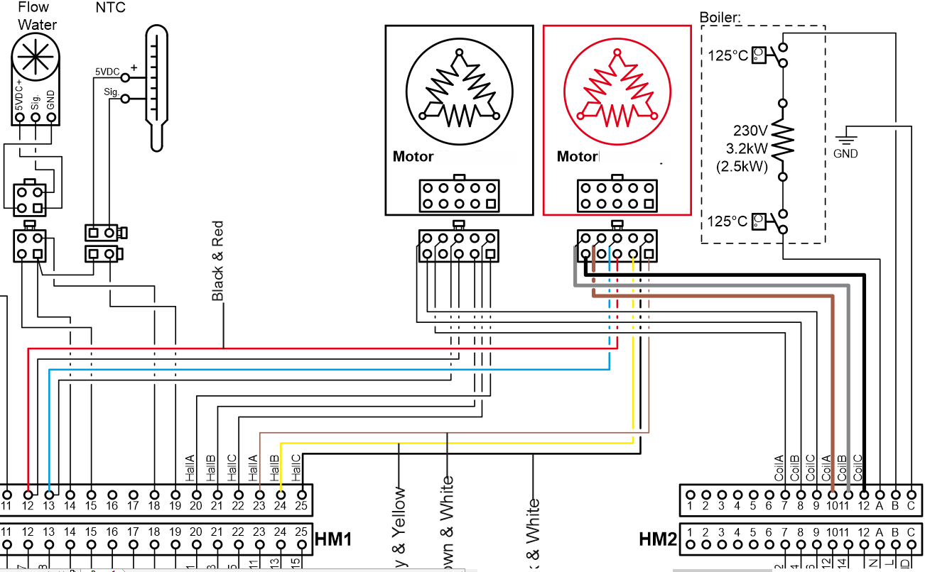
3 Phase Brushless DC Motors Motors Control DroneBot Workshop Forums
The image title is 3 Phase Brushless DC Motors Motors Control DroneBot Workshop Forums, features dimensions of width 1302 px and height 806 px, with a file size of 1302 x 806 px. This image image/png type visual are source from forum.dronebotworkshop.com.
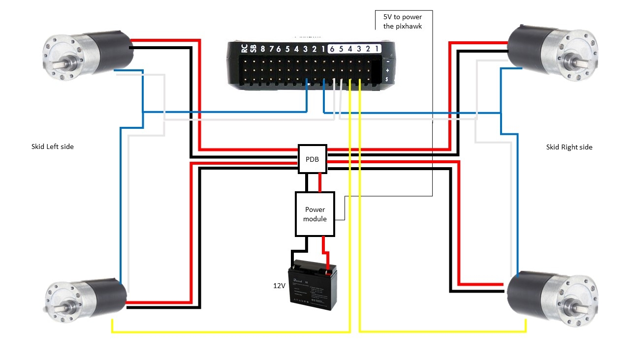
Help Wiring Brushless Motor With Building Encoder Miscellaneous ArduPilot Discourse
The image title is Help Wiring Brushless Motor With Building Encoder Miscellaneous ArduPilot Discourse, features dimensions of width 1280 px and height 720 px, with a file size of 1280 x 720. This image image/jpeg type visual are source from discuss.ardupilot.org.
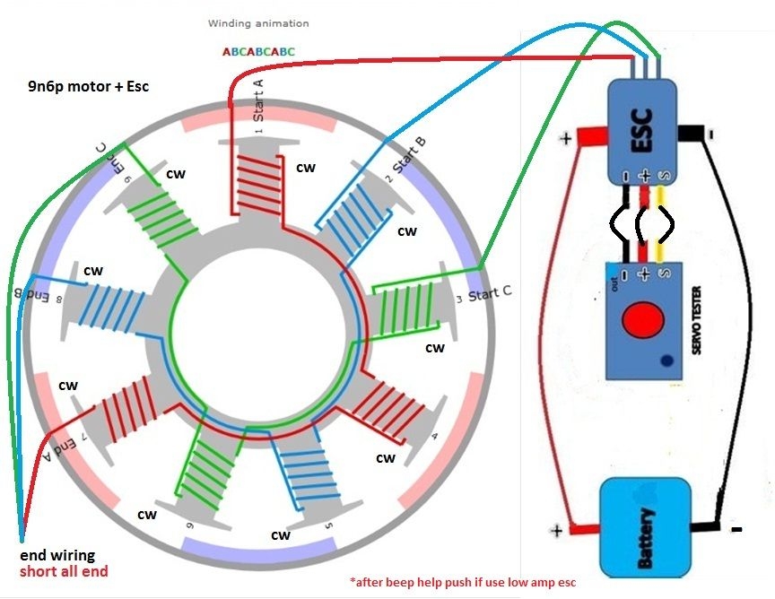
Link Bldc 9n6p Esc Diagram Electrical Wiring Colours Electrical Circuit Diagram Motor
The image title is Link Bldc 9n6p Esc Diagram Electrical Wiring Colours Electrical Circuit Diagram Motor, features dimensions of width 864 px and height 668 px, with a file size of 864 x 668. This image image/jpeg type visual are source from www.pinterest.com.
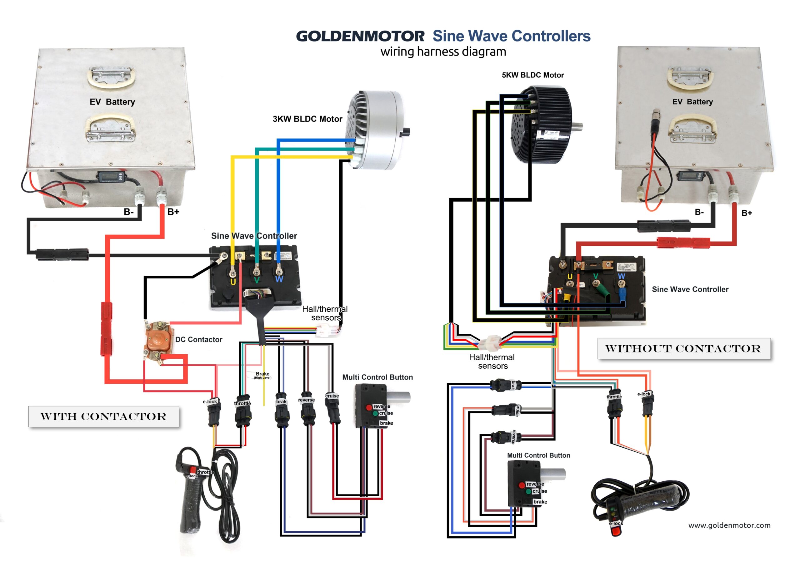
BLDC Motor Vector Controller Wiring Golden Motor North America
The image title is BLDC Motor Vector Controller Wiring Golden Motor North America, features dimensions of width 2560 px and height 1810 px, with a file size of 3508 x 2480. This image image/jpeg type visual are source from goldenmotor.bike
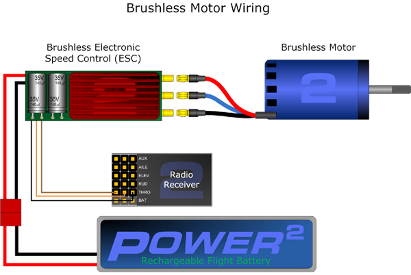
Brushless Motor Wiring Diagram
The image title is Brushless Motor Wiring Diagram, features dimensions of width 600 px and height 402 px, with a file size of 600 x 402. This image image/png type visual are source from www.pinterest.at.
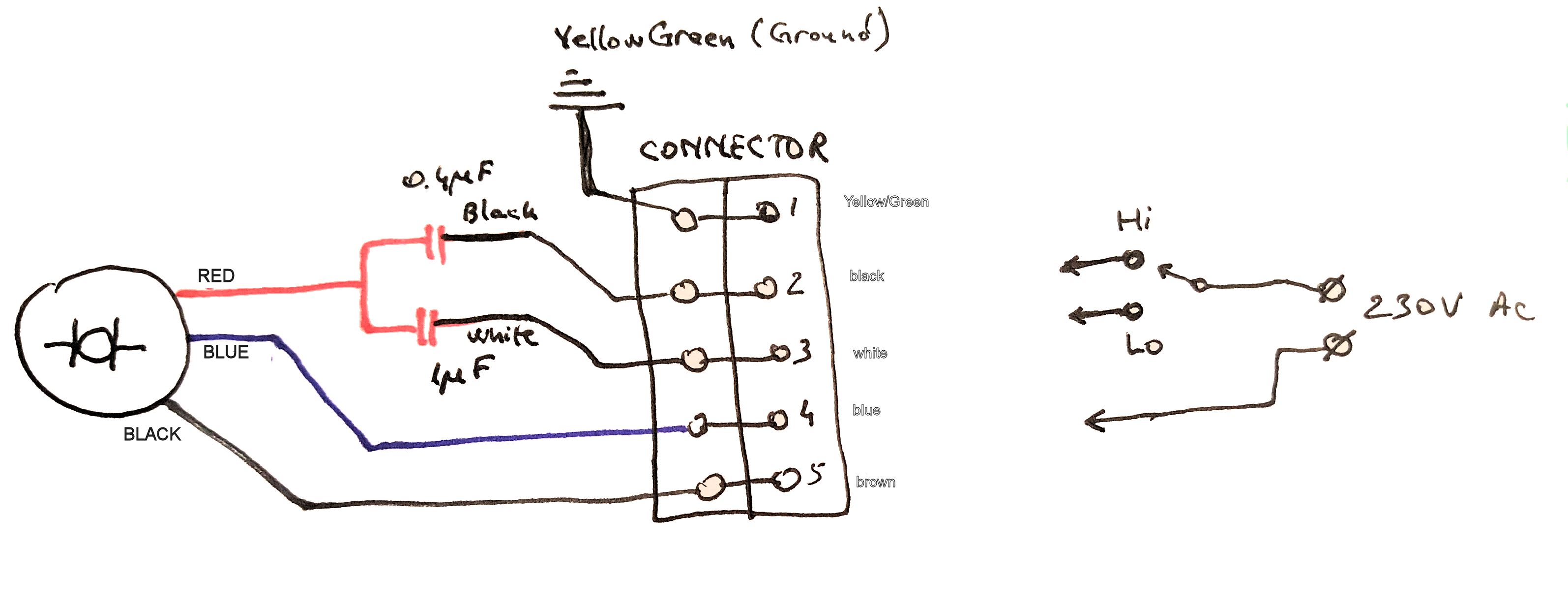
Capacitor How To Connect This 3 Wire AC Motor Electrical Engineering Stack Exchange
The image title is Capacitor How To Connect This 3 Wire AC Motor Electrical Engineering Stack Exchange, features dimensions of width 3189 px and height 1234 px, with a file size of 3189 x 1234. This image image/png type visual are source from electronics.stackexchange.com.
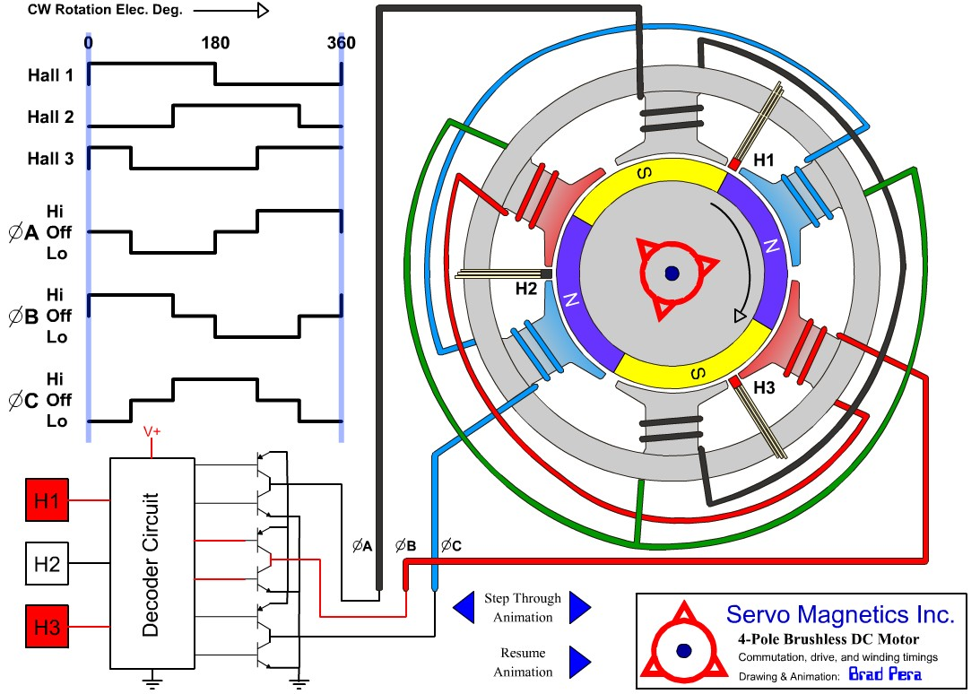
Why Do Brushless Motors Have 3 Wires Compared To 2 Wires On A Brushed Motor Drones And Model Aircraft Stack Exchange
The image title is Why Do Brushless Motors Have 3 Wires Compared To 2 Wires On A Brushed Motor Drones And Model Aircraft Stack Exchange, features dimensions of width 1093 px and height 774 px, with a file size of 1093 x 774.
The images on this page, sourced from Google for educational purposes, may be copyrighted. If you own an image and wish its removal or have copyright concerns, please contact us. We aim to promptly address these issues in compliance with our copyright policy and DMCA standards. Your cooperation is appreciated.
Related Keywords to 3 Wire Brushless Motor Wiring Diagram:
3 wire brushless motor wiring diagram,how does a 3 wire dc motor work,how to wire 3 wire brushless motor,what are the 3 wires on a brushless motor,why does my dc motor have 3 wires
