Table of Contents
Exploring the 3 Wire Crank Position Sensor Wiring Diagram
The Value of 3 Wire Crank Position Sensor Wiring Diagram
Understanding the intricacies of a 3 wire crank position sensor wiring diagram is crucial for anyone delving into automotive maintenance or repair. This diagram serves as a roadmap, guiding individuals through the complex network of wires and connections that make up the sensor system. By comprehending the wiring diagram, technicians can troubleshoot issues more effectively, identify potential faults, and ensure proper functioning of the crank position sensor. Let’s delve into the world of 3 wire crank position sensor wiring diagrams and unravel the mysteries they hold.
The Basics of a Crank Position Sensor
Before diving into the wiring diagram, it’s essential to grasp the fundamentals of a crank position sensor. This sensor plays a vital role in the engine management system, providing crucial data about the position of the crankshaft. By detecting the rotational speed and position of the crankshaft, the sensor enables the engine control unit to synchronize fuel injection and ignition timing. A malfunctioning crank position sensor can lead to a host of issues, including stalling, rough idling, and poor performance.
Components of a 3 Wire Crank Position Sensor
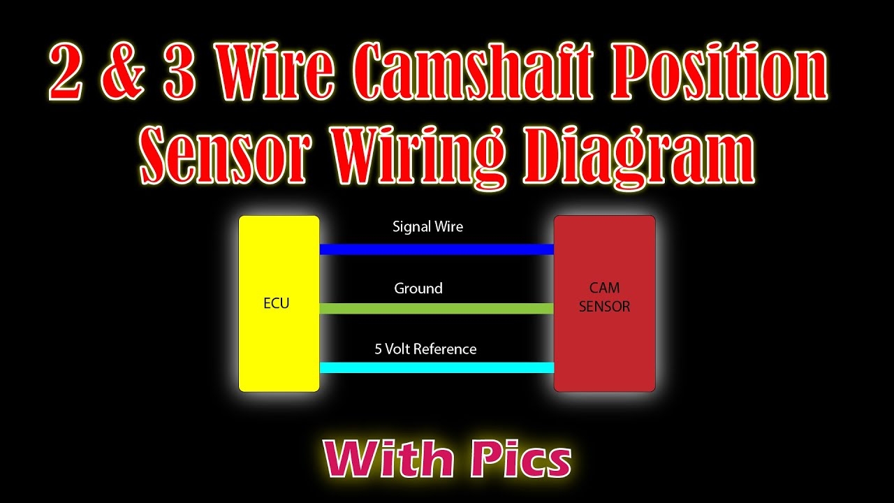
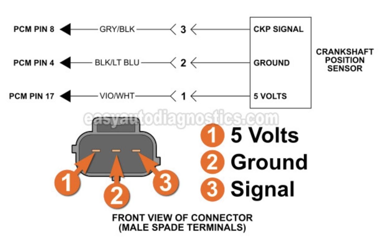
A 3 wire crank position sensor typically comprises three wires: power supply, ground, and signal output. The power supply wire delivers voltage to the sensor, the ground wire completes the circuit and provides a return path for current, and the signal output wire transmits data to the engine control unit. Each wire plays a crucial role in ensuring the sensor functions correctly, and any disruptions in these connections can result in sensor failure.
Interpreting the Wiring Diagram
The wiring diagram for a 3 wire crank position sensor outlines the specific connections between the sensor and other components in the engine system. By deciphering this diagram, technicians can pinpoint the exact wiring configuration, identify potential faults, and troubleshoot issues effectively. Understanding the color codes, pin assignments, and wire routing depicted in the diagram is essential for maintaining the integrity of the sensor system.
Common Wiring Configurations
In a 3 wire crank position sensor wiring diagram, common configurations include connecting the power supply wire to a switched 12V source, grounding the ground wire to the engine block or chassis, and routing the signal output wire to the engine control unit. Following these configurations ensures proper functioning of the sensor and prevents electrical faults that could disrupt sensor operation.
Troubleshooting and Maintenance Tips
When dealing with a 3 wire crank position sensor, certain troubleshooting and maintenance tips can be invaluable. Regularly inspecting the wiring connections for wear or corrosion, testing the sensor for continuity and voltage output, and referencing the wiring diagram for guidance are essential practices for ensuring optimal sensor performance. By following these tips, technicians can prevent potential issues and address any concerns promptly.
Related to 3 Wire Crank Position Sensor Wiring Diagram
- 3 Wire Bilge Pump Wiring Diagram
- 3 Wire Brake Light Turn Signal Wiring Diagram
- 3 Wire Brushless Motor Wiring Diagram
- 3 Wire Ceiling Fan Wiring Diagram
- 3 Wire Condenser Fan Motor Wiring Diagram
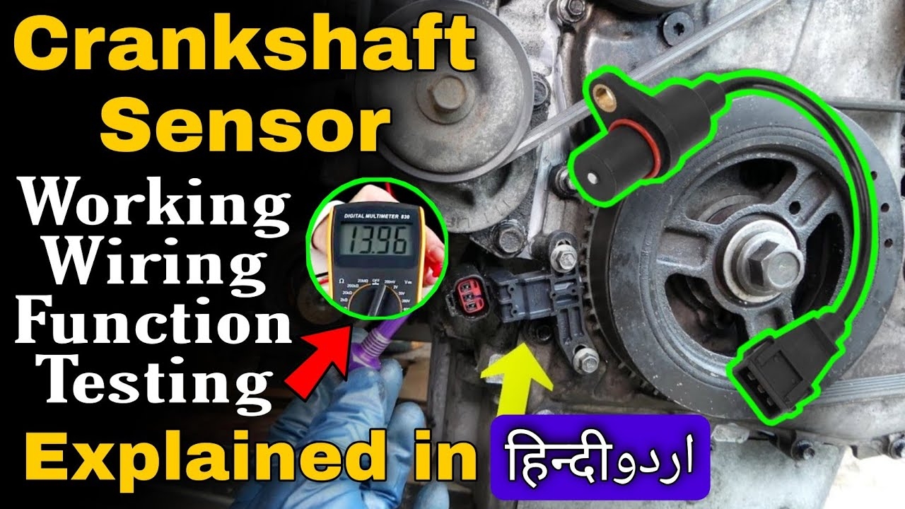
Crankshaft Position Sensor Wiring Diagram Functions Working Testing P0335 P0336 P0337 YouTube
The image title is Crankshaft Position Sensor Wiring Diagram Functions Working Testing P0335 P0336 P0337 YouTube, features dimensions of width 1280 px and height 720 px, with a file size of 1280 x 720 px. This image image/jpeg type visual are source from m.youtube.com.
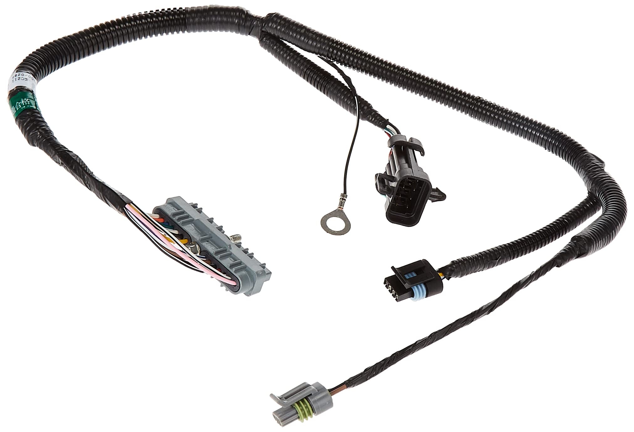
Amazon Dorman 645 688 Cam Crank And Ignition Harness Compatible With Select Models Automotive
The image title is Amazon Dorman 645 688 Cam Crank And Ignition Harness Compatible With Select Models Automotive, features dimensions of width 2024 px and height 1378 px, with a file size of 2024 x 1378 px. This image image/jpeg type visual are source from www.amazon.com.
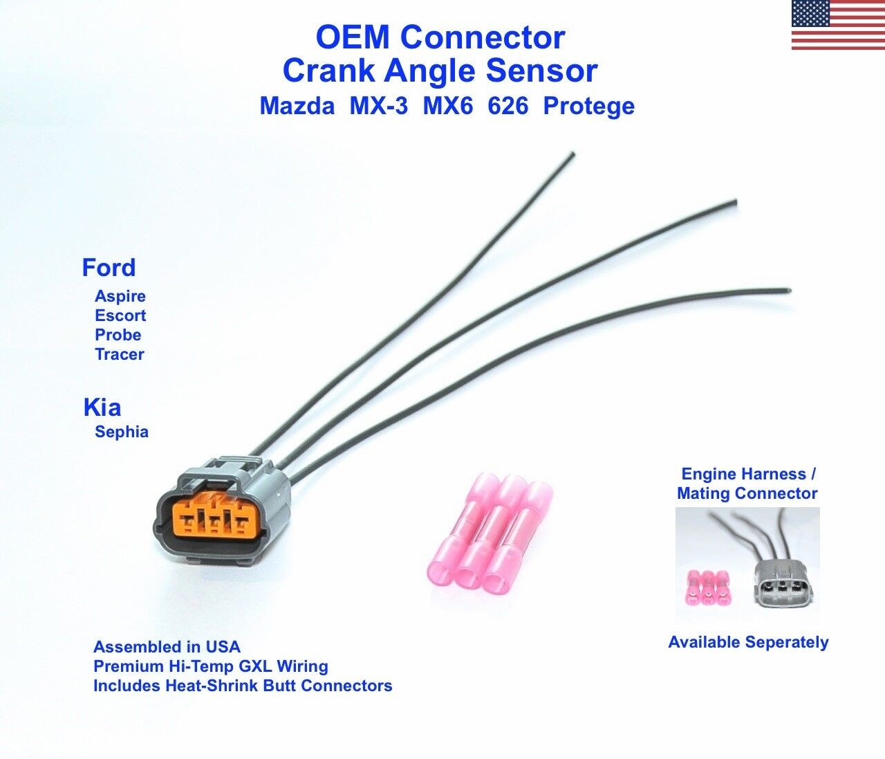
Mazda Protege Crankshaft Position Sensor Connector Plug Pigtail Crank Angle CAS EBay
The image title is Mazda Protege Crankshaft Position Sensor Connector Plug Pigtail Crank Angle CAS EBay, features dimensions of width 1280 px and height 1097 px, with a file size of 1280 x 1097. This image image/jpeg type visual are source from www.ebay.com.
2 3 Wire Camshaft Position Wiring Diagram Easy Car Electrics YouTube
The image title is 2 3 Wire Camshaft Position Wiring Diagram Easy Car Electrics YouTube, features dimensions of width 1280 px and height 720 px, with a file size of 1280 x 720. This image image/jpeg type visual are source from www.youtube.com.
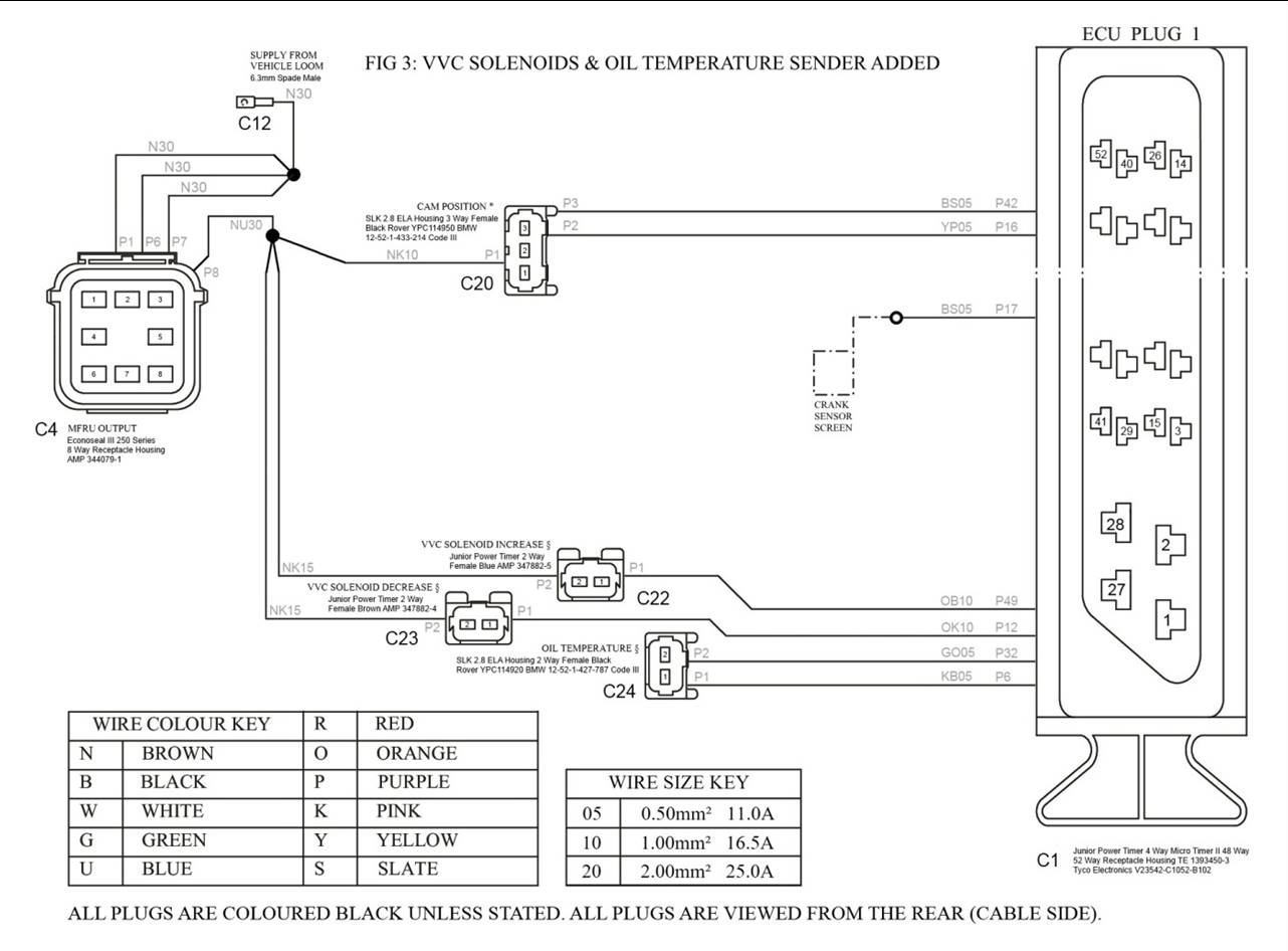
Image119 Jpg
The image title is Image119 Jpg, features dimensions of width 1282 px and height 946 px, with a file size of 1282 x 946. This image image/jpeg type visual are source from andrewrevill.co.uk
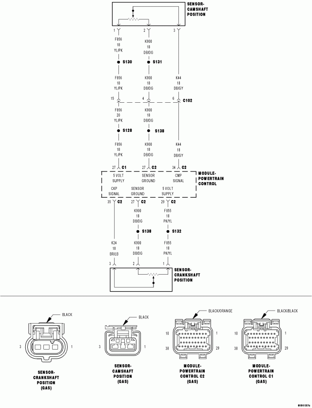
P0339 Crankshaft Position Sensor Intermittent
The image title is P0339 Crankshaft Position Sensor Intermittent, features dimensions of width 640 px and height 838 px, with a file size of 640 x 838. This image image/gif type visual are source from s3.amazonaws.com.
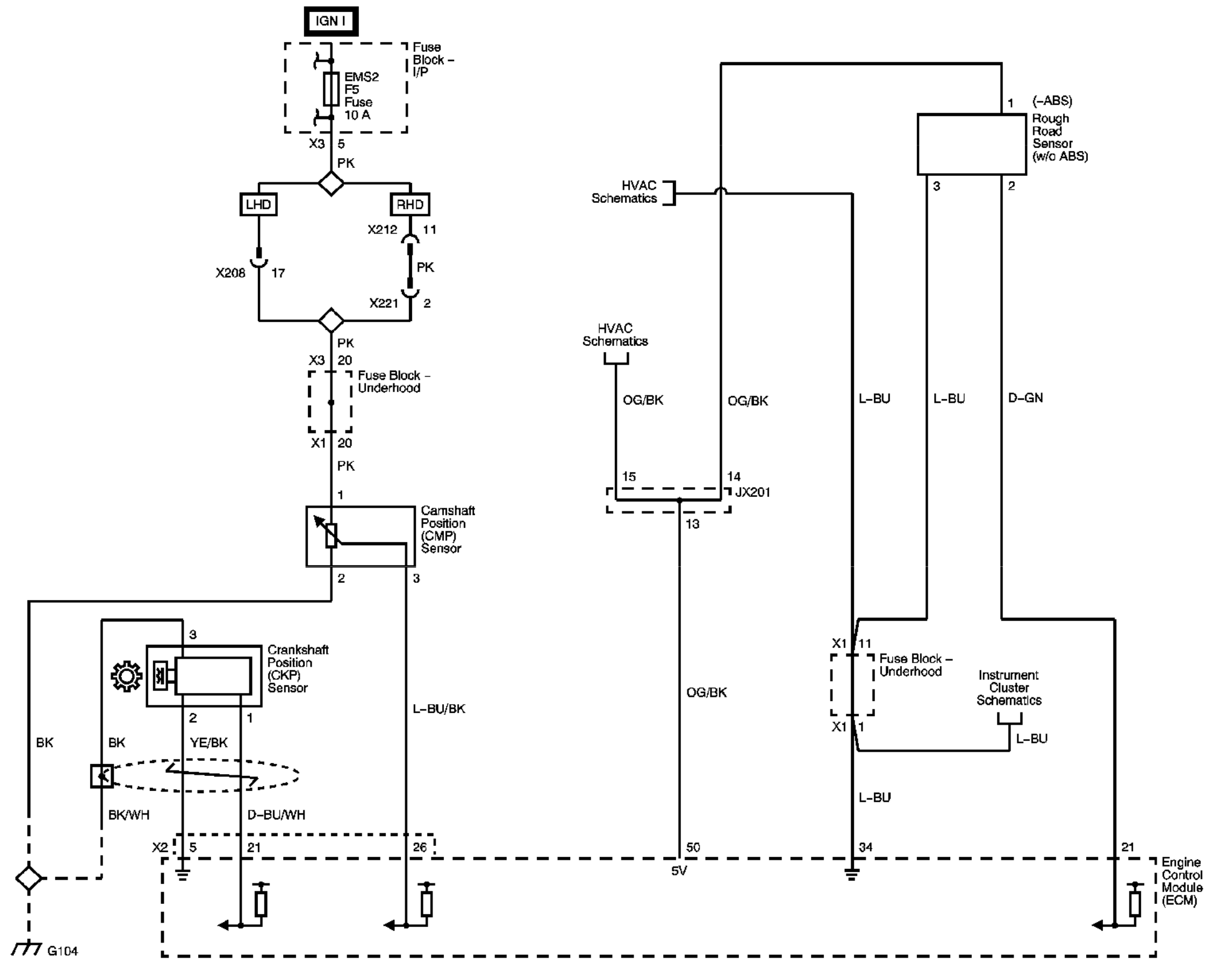
Automotive How To Wire Up Camshaft Position Sensor In Lab Environment Electrical Engineering Stack Exchange
The image title is Automotive How To Wire Up Camshaft Position Sensor In Lab Environment Electrical Engineering Stack Exchange, features dimensions of width 2028 px and height 1623 px, with a file size of 2028 x 1623. This image image/png type visual are source from electronics.stackexchange.com.
Wiring Advice Focus 1 6 TDCI 2011 Crankshaft Sensor Ford Focus Club Ford Owners Club Ford Forums
The image title is Wiring Advice Focus 1 6 TDCI 2011 Crankshaft Sensor Ford Focus Club Ford Owners Club Ford Forums, features dimensions of width 1232 px and height 765 px, with a file size of 1232 x 765.
The images on this page, sourced from Google for educational purposes, may be copyrighted. If you own an image and wish its removal or have copyright concerns, please contact us. We aim to promptly address these issues in compliance with our copyright policy and DMCA standards. Your cooperation is appreciated.
Related Keywords to 3 Wire Crank Position Sensor Wiring Diagram:
3 wire crank position sensor wiring diagram,crankshaft position sensor wire colors,how does a 2 wire crank sensor work,how does a 3 wire crank sensor work,how to test a 3 wire crankshaft position sensor
