Table of Contents
The Ultimate Guide to P.T.O. Switch Wiring Diagram
The Ultimate Guide to P.T.O. Switch Wiring Diagram
When it comes to the intricate world of electrical systems in vehicles or machinery, having a reliable wiring diagram is essential. One crucial component that demands precision and clarity in its wiring is the Power Take-Off (P.T.O.) switch. A P.T.O. switch wiring diagram serves as a roadmap for ensuring a seamless connection between the switch and the equipment it controls. With the right wiring diagram, troubleshooting issues, making modifications, or installing a new P.T.O. switch becomes a straightforward task. Let’s delve into the intricacies of P.T.O. switch wiring diagrams and explore how they can streamline your electrical projects.
The Importance of P.T.O. Switch Wiring Diagram
In the realm of automotive or industrial machinery, a P.T.O. switch acts as a pivotal control for engaging or disengaging the power take-off system. This system enables the transmission of power from the engine to auxiliary equipment, such as pumps, generators, or winches. A meticulously crafted wiring diagram for the P.T.O. switch is indispensable for ensuring that the electrical connections are accurate and optimized for efficient operation. By following a comprehensive wiring diagram, technicians can troubleshoot issues effectively, prevent electrical malfunctions, and enhance the overall performance of the equipment.
Key Components of a P.T.O. Switch Wiring Diagram
A well-designed P.T.O. switch wiring diagram typically includes the following key components:
Detailed schematic of the P.T.O. switch circuit
Identification of wire colors and functions
Connection points for power supply and ground
Integration with other electrical systems
Each of these components plays a crucial role in ensuring that the P.T.O. switch functions seamlessly within the broader electrical framework of the vehicle or machinery.
Benefits of Using a P.T.O. Switch Wiring Diagram
Utilizing a P.T.O. switch wiring diagram offers several benefits, including:
Enhanced clarity and organization in wiring connections
Efficient troubleshooting of electrical issues
Facilitation of modifications or upgrades
Compliance with safety and regulatory standards
By harnessing the insights provided by a comprehensive wiring diagram, technicians can work with confidence, knowing that the electrical system is configured correctly and optimized for peak performance.
Steps to Interpret a P.T.O. Switch Wiring Diagram
To effectively interpret a P.T.O. switch wiring diagram, follow these steps:
Identify the P.T.O. switch location and corresponding circuit
Refer to the legend for wire color codes and functions
Trace the wiring connections and verify continuity
Check for any signs of wear, damage, or loose connections
By methodically analyzing the wiring diagram and conducting a thorough inspection, technicians can uncover potential issues, make informed decisions, and execute precise repairs or modifications.
Conclusion
In the realm of electrical systems, precision and accuracy are paramount, particularly when it comes to components like the P.T.O. switch. A meticulously crafted wiring diagram serves as a beacon of guidance, illuminating the path to seamless connectivity and optimal performance. By embracing the insights gleaned from a P.T.O. switch wiring diagram, technicians can navigate complex electrical systems with confidence, efficiency, and precision.
Related to P.T.O. Switch Wiring Diagram
- Outlet With Switch Wiring Diagram
- Overload Refrigerator Start Relay Wiring Diagram
- Oxygen Sensor Wiring Diagram
- P Bass Wiring Diagram
- P J Bass Wiring Diagram
1990 312 8 PTO NEUTRAL SWITCH Wheel Horse Electrical RedSquare Wheel Horse Forum
The image title is 1990 312 8 PTO NEUTRAL SWITCH Wheel Horse Electrical RedSquare Wheel Horse Forum, features dimensions of width 592 px and height 768 px, with a file size of 592 x 768 px. This image image/jpeg type visual are source from www.wheelhorseforum.com.
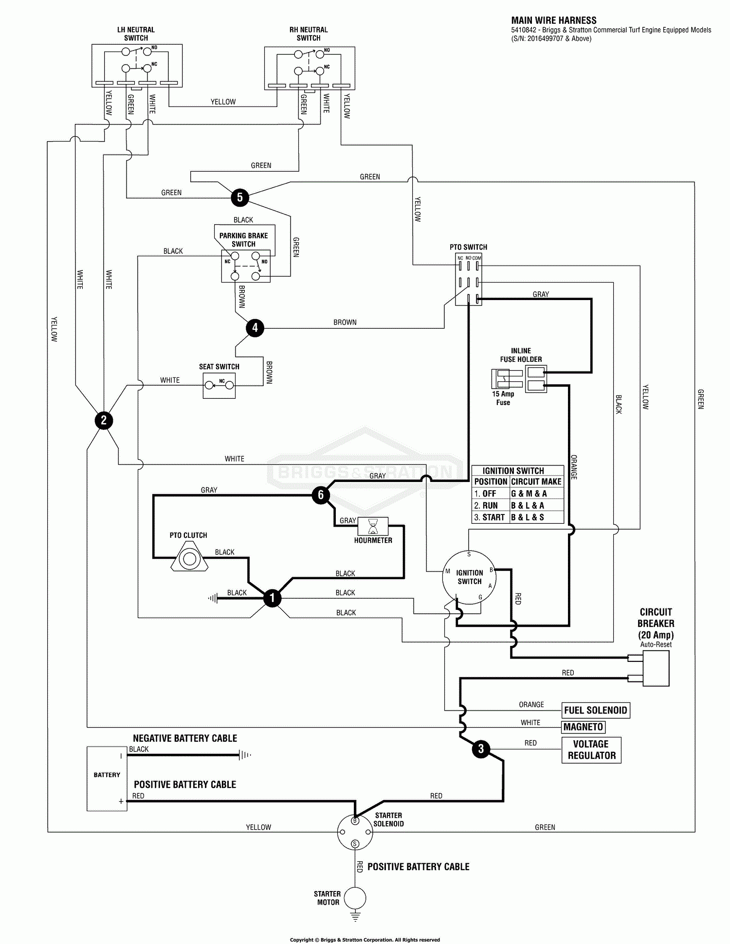
Snapper Pro 5900959 S50XTBS2748 48 Mid Mount Zero Turn Rider Parts Diagram For Electrical Schematic PTO Clutch Circuit B S S N 2016499707 Above
The image title is Snapper Pro 5900959 S50XTBS2748 48 Mid Mount Zero Turn Rider Parts Diagram For Electrical Schematic PTO Clutch Circuit B S S N 2016499707 Above, features dimensions of width 1500 px and height 1941 px, with a file size of 1500 x 1941 px. This image image/gif type visual are source from www.jackssmallengines.com.
Rocker Switch Wiring Diagrams New Wire Marine
The image title is Rocker Switch Wiring Diagrams New Wire Marine, features dimensions of width 800 px and height 1035 px, with a file size of 800 x 1035. This image image/jpeg type visual are source from newwiremarine.com.
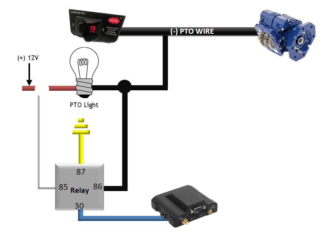
Overview Guide Relays Device Help
The image title is Overview Guide Relays Device Help, features dimensions of width 1106 px and height 796 px, with a file size of 1106 x 796. This image image/png type visual are source from install.verizonconnect.com.
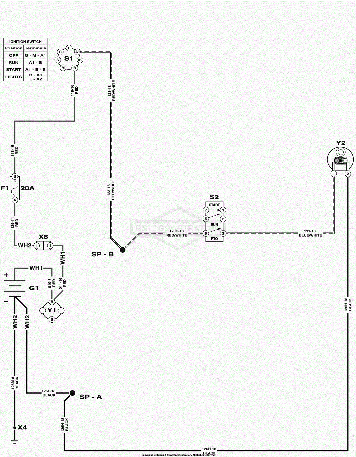
Snapper 2691557 00 SPX2346 46 23 HP SPX Lawn Tractor 150 Series Parts Diagram For Electrical Schematic PTO Clutch
The image title is Snapper 2691557 00 SPX2346 46 23 HP SPX Lawn Tractor 150 Series Parts Diagram For Electrical Schematic PTO Clutch, features dimensions of width 1500 px and height 1925 px, with a file size of 1500 x 1925. This image image/gif type visual are source from www.jackssmallengines.com
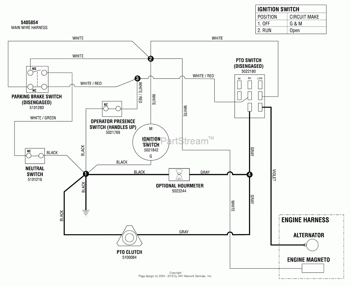
Snapper Pro 5900964 SW30KAV1848 48 Walk Behind Mower Parts Diagram For Electrical Schematic PTO Clutch Circuit Manual Start Kawasaki
The image title is Snapper Pro 5900964 SW30KAV1848 48 Walk Behind Mower Parts Diagram For Electrical Schematic PTO Clutch Circuit Manual Start Kawasaki, features dimensions of width 1180 px and height 961 px, with a file size of 1180 x 961. This image image/gif type visual are source from www.jackssmallengines.com.
Electric Pto Problem John Deere Tractor Forum John Deere Electrical Diagram John Deere Tractors
The image title is Electric Pto Problem John Deere Tractor Forum John Deere Electrical Diagram John Deere Tractors, features dimensions of width 507 px and height 477 px, with a file size of 507 x 477. This image image/jpeg type visual are source from www.pinterest.com.
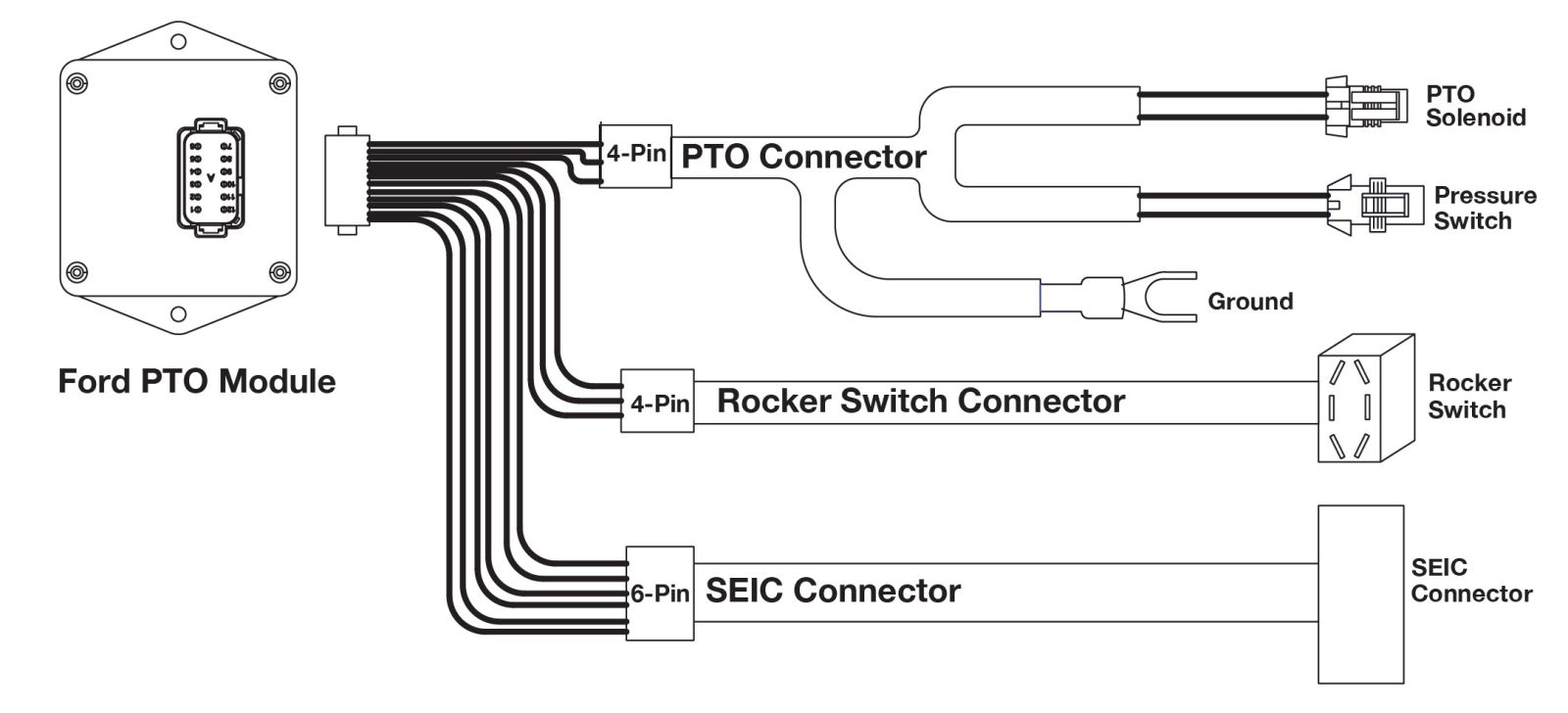
How To Install And Program The PTO RPM Module On Ford Trucks
The image title is How To Install And Program The PTO RPM Module On Ford Trucks, features dimensions of width 1600 px and height 728 px, with a file size of 1600 x 728.
The images on this page, sourced from Google for educational purposes, may be copyrighted. If you own an image and wish its removal or have copyright concerns, please contact us. We aim to promptly address these issues in compliance with our copyright policy and DMCA standards. Your cooperation is appreciated.
Related Keywords to P.T.O. Switch Wiring Diagram:
chelsea p.t.o. switch wiring diagram,how does pto switch work,how to wire a pto switch,what is a pto switch

