Table of Contents
The Ultimate Guide to Oxygen Sensor Wiring Diagrams
The Value of Oxygen Sensor Wiring Diagrams
When it comes to diagnosing and troubleshooting issues with your vehicle’s oxygen sensor, having a comprehensive wiring diagram can make all the difference. An oxygen sensor plays a crucial role in monitoring and regulating the air-fuel mixture in your car’s engine, ensuring optimal performance and fuel efficiency. Understanding the wiring connections and voltages of the oxygen sensor is essential for accurate diagnostics and repairs. In this guide, we will delve into the intricacies of oxygen sensor wiring diagrams, providing you with the knowledge and insights you need to keep your vehicle running smoothly.
Understanding Oxygen Sensor Wiring Diagrams
1. Components of an Oxygen Sensor Wiring Diagram
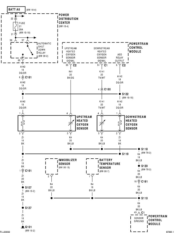
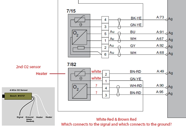
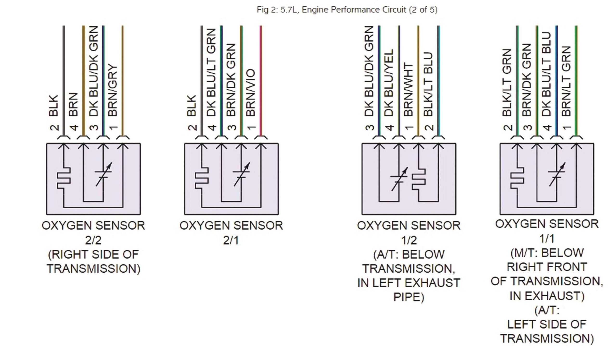
An oxygen sensor wiring diagram typically includes information about the sensor’s power supply, ground connection, signal wire, and heater circuit. These components are essential for the proper functioning of the oxygen sensor and are interconnected in a specific way to ensure accurate readings and feedback to the vehicle’s engine control module.
2. Interpreting the Wiring Color Codes
In oxygen sensor wiring diagrams, different wire colors are used to represent various connections. Understanding the meaning of these color codes is crucial for correctly identifying and troubleshooting issues with the sensor’s wiring. By familiarizing yourself with the standard color codes used in oxygen sensor wiring diagrams, you can quickly pinpoint any faults or discrepancies in the wiring harness.
Common Issues and Solutions
1. Faulty Sensor Signal
One of the most common issues with oxygen sensors is a faulty signal due to damaged wiring or poor connections. By referring to the wiring diagram, you can trace the signal wire from the sensor to the engine control module and check for any breaks or frays that may be causing signal disruptions. Repairing or replacing the affected wiring can restore proper sensor functionality and improve engine performance.
2. Heater Circuit Malfunction
Another frequent problem with oxygen sensors is a malfunctioning heater circuit, which can lead to slow sensor response times and inaccurate readings. By examining the wiring diagram, you can locate the heater circuit connections and test the continuity and resistance of the circuit to identify any faults. Repairing or replacing the heater circuit components can resolve heating issues and ensure optimal sensor operation.
Conclusion
In conclusion, oxygen sensor wiring diagrams are invaluable tools for diagnosing, troubleshooting, and repairing issues related to your vehicle’s oxygen sensor. By understanding the components, connections, and color codes outlined in these diagrams, you can effectively identify and resolve sensor-related problems, ensuring smooth engine operation and optimal fuel efficiency. Keep this guide handy the next time you encounter issues with your oxygen sensor, and harness the power of wiring diagrams to keep your vehicle running smoothly.
Related to Oxygen Sensor Wiring Diagram
- Outlet Diagram Wiring
- Outlet Switch Wiring Diagram
- Outlet Wiring Diagram
- Outlet With Switch Wiring Diagram
- Overload Refrigerator Start Relay Wiring Diagram
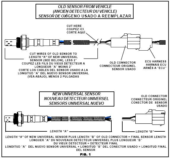
Sensor Schematics At DuckDuckGo Electronic Schematics Sensor Diagram
The image title is Sensor Schematics At DuckDuckGo Electronic Schematics Sensor Diagram, features dimensions of width 574 px and height 534 px, with a file size of 574 x 534 px. This image image/jpeg type visual are source from www.pinterest.com.
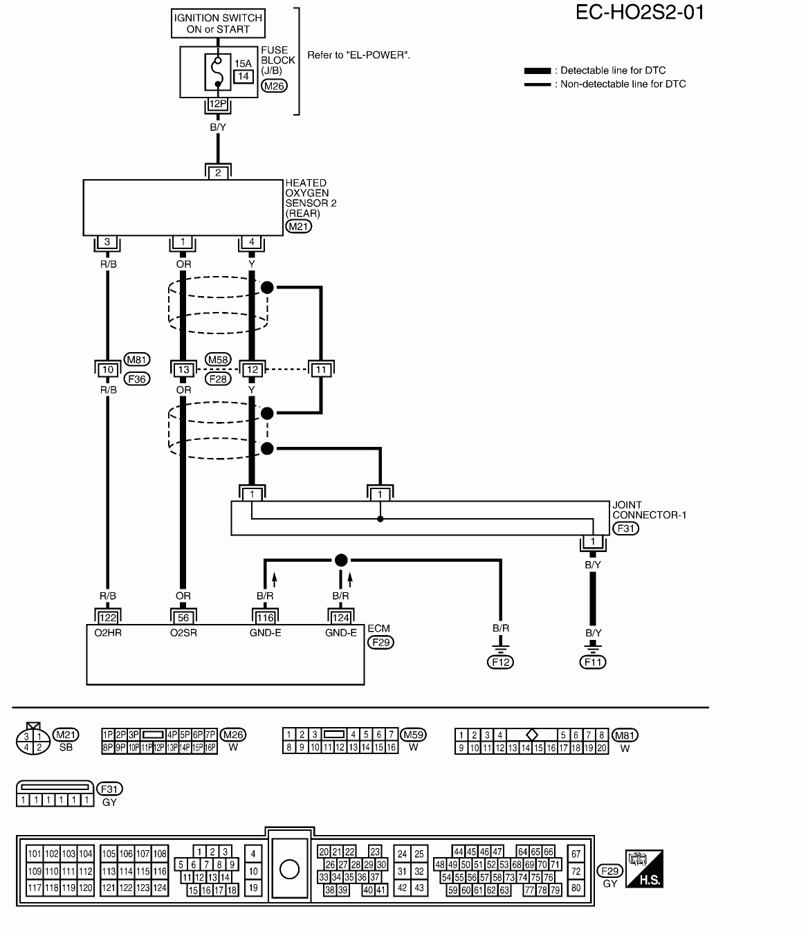
Nissan Frontier Oxygen Sensor Wiring Diagram Q A For Bank 1 Sensor 1 2 JustAnswer
The image title is Nissan Frontier Oxygen Sensor Wiring Diagram Q A For Bank 1 Sensor 1 2 JustAnswer, features dimensions of width 1168 px and height 1353 px, with a file size of 1168 x 1353 px. This image image/gif type visual are source from www.justanswer.com.
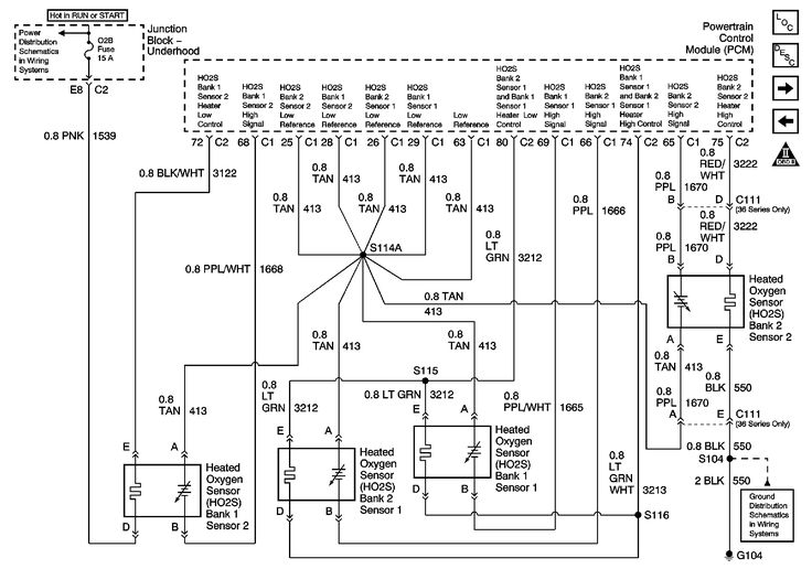
GM O2 Sensor Wiring Diagram Sensors 2001 02 6 0l With Isolated Ground Sensors Only Sensor Diagram Engineering
The image title is GM O2 Sensor Wiring Diagram Sensors 2001 02 6 0l With Isolated Ground Sensors Only Sensor Diagram Engineering, features dimensions of width 736 px and height 516 px, with a file size of 736 x 516. This image image/jpeg type visual are source from www.pinterest.com.
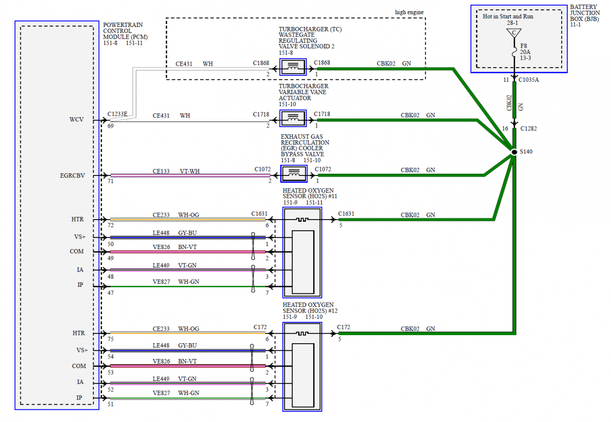
Oxygen Sensor Testing Wiring Diagram Confusion 2 0L EcoBoost Ford Edge Forum
The image title is Oxygen Sensor Testing Wiring Diagram Confusion 2 0L EcoBoost Ford Edge Forum, features dimensions of width 1200 px and height 830 px, with a file size of 1200 x 830. This image image/png type visual are source from www.fordedgeforum.com.
O2 Sensor Wiring Diagram Neons
The image title is O2 Sensor Wiring Diagram Neons, features dimensions of width 600 px and height 799 px, with a file size of 600 x 799. This image image/jpeg type visual are source from forums.neons.org
Wiring Diagram Help O2 Sensor SwedeSpeed Volvo Performance Forum
The image title is Wiring Diagram Help O2 Sensor SwedeSpeed Volvo Performance Forum, features dimensions of width 604 px and height 433 px, with a file size of 604 x 433. This image image/jpeg type visual are source from www.swedespeed.com.
Tracing Sensor Wiring And Checking For Lazy Sensors Issuu
The image title is Tracing Sensor Wiring And Checking For Lazy Sensors Issuu, features dimensions of width 2560 px and height 1475 px, with a file size of 2702 x 1557. This image image/jpeg type visual are source from issuu.com.
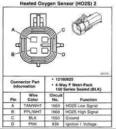
Oxygen Sensor Wiring Diagram For Toyota
The image title is Oxygen Sensor Wiring Diagram For Toyota, features dimensions of width 235 px and height 262 px, with a file size of 235 x 262.
The images on this page, sourced from Google for educational purposes, may be copyrighted. If you own an image and wish its removal or have copyright concerns, please contact us. We aim to promptly address these issues in compliance with our copyright policy and DMCA standards. Your cooperation is appreciated.
Related Keywords to Oxygen Sensor Wiring Diagram:
02 sensor wiring diagram,lambda sensor wiring diagram,oxygen sensor circuit diagram,oxygen sensor wiring diagram,oxygen sensor wiring diagram toyota
