Table of Contents
The Ultimate Guide to Fisher Plow Solenoid Wiring Diagram
The Value of Fisher Plow Solenoid Wiring Diagram
When it comes to installing or troubleshooting a Fisher plow solenoid, having a comprehensive wiring diagram at your disposal can make all the difference. The Fisher plow solenoid wiring diagram serves as a roadmap to understanding the intricate connections within the plow system, ensuring that every wire is in its rightful place. This invaluable resource not only aids in the installation process but also simplifies the troubleshooting of any electrical issues that may arise. Let’s delve deeper into the world of Fisher plow solenoid wiring diagrams and uncover the key insights they offer.
Understanding Fisher Plow Solenoid Wiring
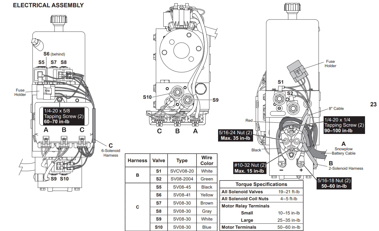
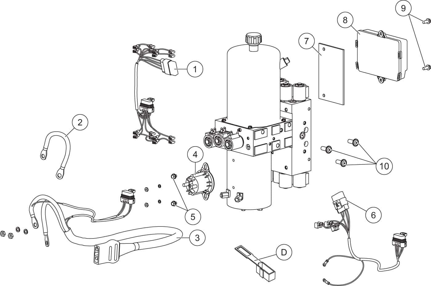
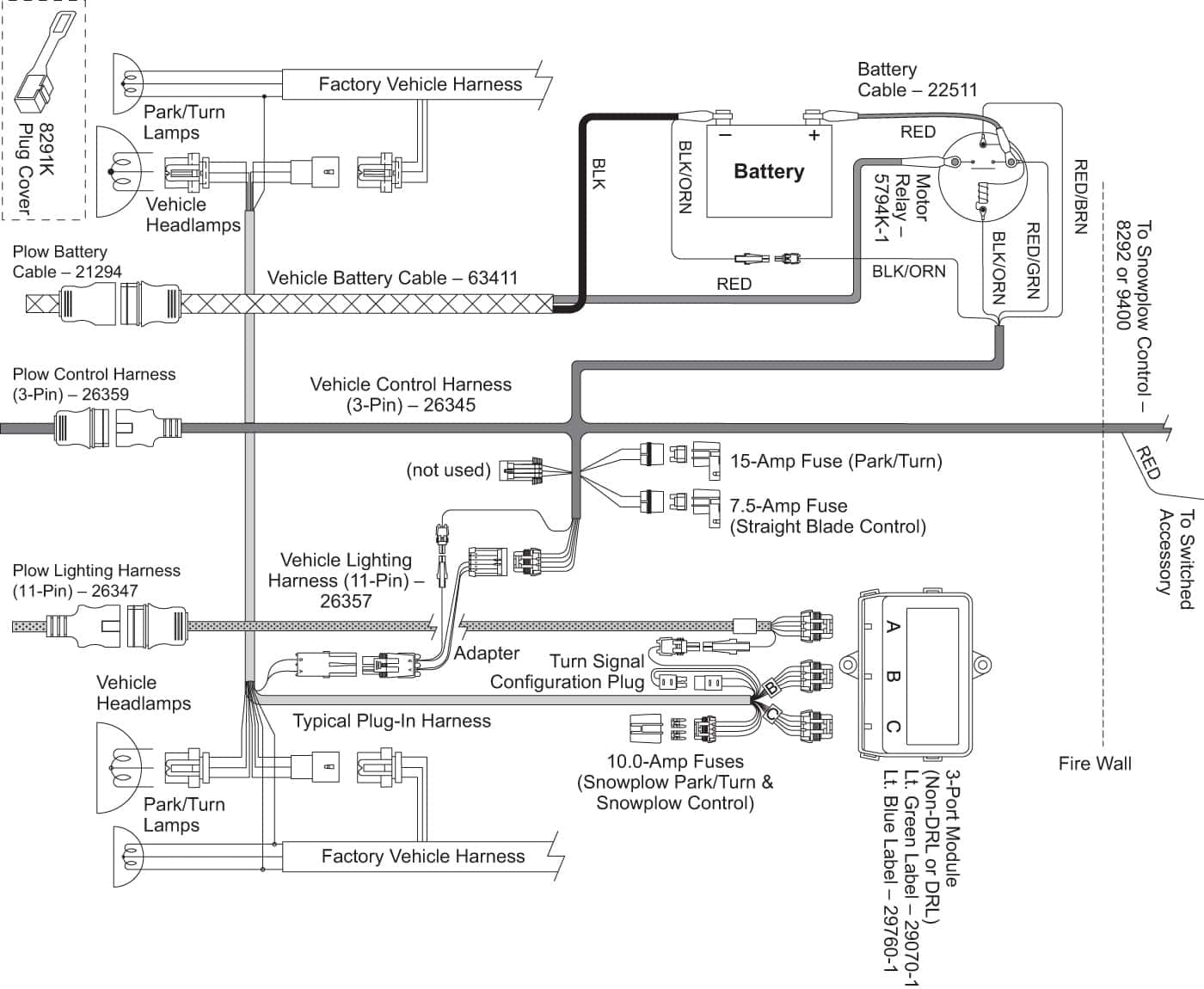
The Fisher plow solenoid wiring diagram is a visual representation of the electrical connections required for the proper functioning of the plow system. It outlines the various components, such as the solenoid, battery, controller, and motor, and illustrates how they are interconnected through a series of wires. By following the diagram closely, users can ensure that each wire is correctly routed and connected, preventing miswiring and potential damage to the system.
Benefits of Using a Wiring Diagram
Ensures Proper Installation: By following the wiring diagram, users can install the Fisher plow solenoid with precision, avoiding any guesswork or errors.
Aids in Troubleshooting: When encountering electrical issues, the wiring diagram serves as a troubleshooting tool, allowing users to identify and rectify any wiring faults efficiently.
Promotes System Reliability: Proper wiring as per the diagram ensures that the plow system operates smoothly and reliably, minimizing the risk of malfunctions.
Components of a Fisher Plow Solenoid Wiring Diagram
A typical Fisher plow solenoid wiring diagram includes labels for each wire, indicating their functions and connections. It also highlights the relay, fuse, and other crucial components that play a role in the electrical system of the plow. Understanding the purpose of each wire and component is essential for successful installation and troubleshooting.
Installation Guide for Fisher Plow Solenoid
Refer to the wiring diagram provided by Fisher to identify the correct wiring connections.
Disconnect the battery to prevent any electrical mishaps during the installation process.
Connect the wires according to the diagram, ensuring a secure and proper connection for each component.
Test the plow system to verify that all electrical functions are working correctly.
Final Thoughts
In conclusion, the Fisher plow solenoid wiring diagram is an indispensable tool for anyone working with Fisher plow systems. Whether you are installing a new solenoid or troubleshooting an existing one, having a clear understanding of the wiring connections is crucial for a successful outcome. By following the guidance provided in the wiring diagram, users can ensure the proper functioning and longevity of their Fisher plow solenoid. Embrace the power of knowledge that a wiring diagram brings, and elevate your plowing experience to new heights.
Related to Fisher Plow Solenoid Wiring Diagram
- Fire Alarm Wiring Diagram
- Firing Order 5.7 Hemi Spark Plug Wiring Diagram
- Fisher Minute Mount 2 Wiring Diagram
- Fisher Plow Controller Wiring Diagram
- Fisher Plow Minute Mount 2 Wiring Diagram
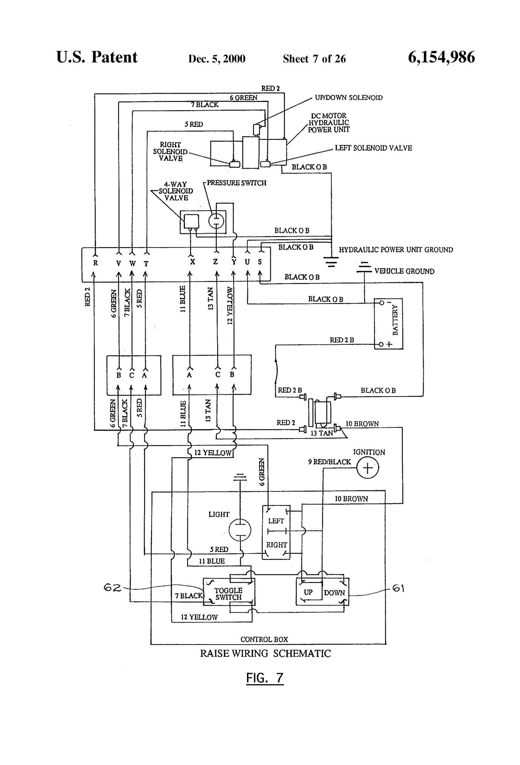
Western Plow Controller Wiring Diagram In 2024 Diagram Electrical Wiring Diagram Snow Plow
The image title is Western Plow Controller Wiring Diagram In 2024 Diagram Electrical Wiring Diagram Snow Plow, features dimensions of width 1743 px and height 2560 px, with a file size of 2320 x 3408 px. This image image/jpeg type visual are source from www.pinterest.com.
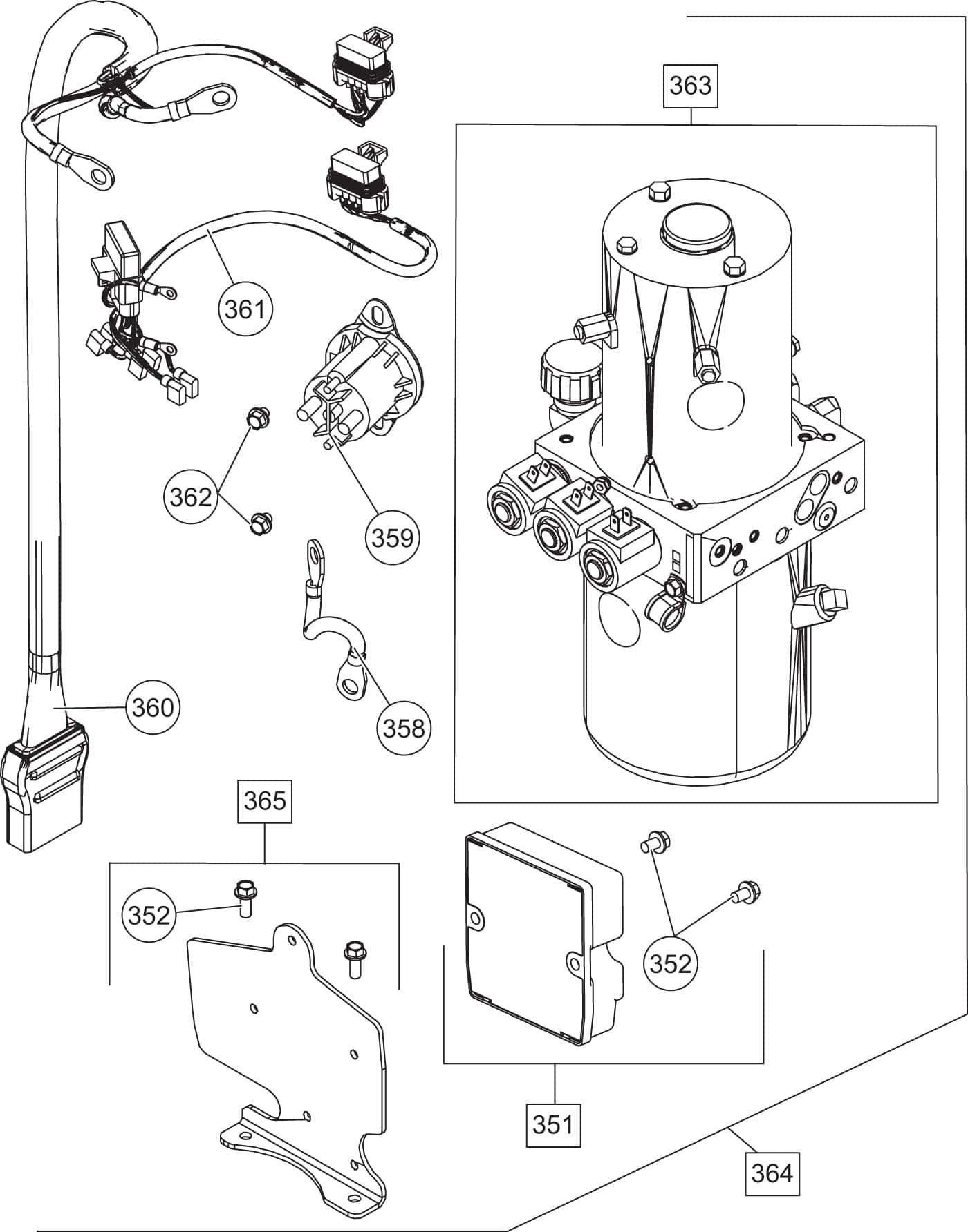
Fisher SDS EC SD Series Electrical Components Shop ITEParts
The image title is Fisher SDS EC SD Series Electrical Components Shop ITEParts, features dimensions of width 1400 px and height 1784 px, with a file size of 1400 x 1784 px. This image image/jpeg type visual are source from iteparts.com.
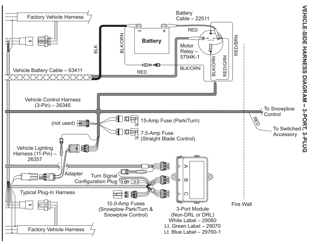
SHOP SNOWPLOW PARTS GENUINE FISHER SNOWPLOWS REPLACEMENT PARTS MINUTE MOUNT 2 PARTS MINUTE MOUNT 2 THREE PLUG PLOWS STRAIGHT PLOWS TRUCK SIDE COMMON WIRING ASH SUPPLY COMPANY LLC
The image title is SHOP SNOWPLOW PARTS GENUINE FISHER SNOWPLOWS REPLACEMENT PARTS MINUTE MOUNT 2 PARTS MINUTE MOUNT 2 THREE PLUG PLOWS STRAIGHT PLOWS TRUCK SIDE COMMON WIRING ASH SUPPLY COMPANY LLC, features dimensions of width 1023 px and height 782 px, with a file size of 1023 x 782. This image image/png type visual are source from www.fishersnowplowparts.com.
Fisher XV2 V Plow Diagram Shop ITEParts
The image title is Fisher XV2 V Plow Diagram Shop ITEParts, features dimensions of width 1400 px and height 894 px, with a file size of 1400 x 894. This image image/jpeg type visual are source from iteparts.com.
29471 FISHER WESTERN PLOW HARNESS 6 SOLENOID KIT FLEETFLEX GENUINE FISHER SNOW PLOW REPLACEMENT PARTS
The image title is 29471 FISHER WESTERN PLOW HARNESS 6 SOLENOID KIT FLEETFLEX GENUINE FISHER SNOW PLOW REPLACEMENT PARTS, features dimensions of width 1300 px and height 795 px, with a file size of 1300 x 795. This image image/png type visual are source from www.fishersnowplowparts.com
Fisher XV2 V Plow Diagram Shop ITEParts
The image title is Fisher XV2 V Plow Diagram Shop ITEParts, features dimensions of width 1400 px and height 927 px, with a file size of 1400 x 927. This image image/jpeg type visual are source from iteparts.com.
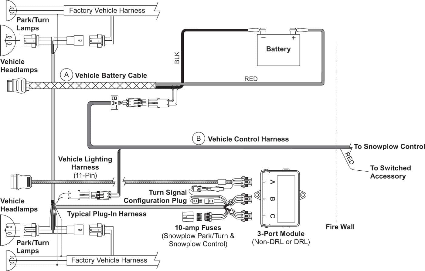
Fisher H VSHD Homesteader Vehicle Side Harness Diagram 3 Port 3 Plug Shop ITEParts
The image title is Fisher H VSHD Homesteader Vehicle Side Harness Diagram 3 Port 3 Plug Shop ITEParts, features dimensions of width 1400 px and height 1150 px, with a file size of 1400 x 1150. This image image/jpeg type visual are source from iteparts.com.
Fisher HD2 EC HD2 Electrical Components Shop ITEParts
The image title is Fisher HD2 EC HD2 Electrical Components Shop ITEParts, features dimensions of width 1400 px and height 955 px, with a file size of 1400 x 955.
The images on this page, sourced from Google for educational purposes, may be copyrighted. If you own an image and wish its removal or have copyright concerns, please contact us. We aim to promptly address these issues in compliance with our copyright policy and DMCA standards. Your cooperation is appreciated.
Related Keywords to Fisher Plow Solenoid Wiring Diagram:
fisher plow solenoid wiring diagram,fisher plow solenoid wiring diagram 3 pin,fisher plow solenoid wiring diagram pdf,fisher snow plow solenoid wiring diagram,snow plow solenoid wiring diagram
