Table of Contents
The Value of Fisher Plow Minute Mount 2 Wiring Diagram
When it comes to installing or troubleshooting a Fisher Minute Mount 2 plow, having access to a comprehensive wiring diagram is invaluable. The Fisher Plow Minute Mount 2 Wiring Diagram serves as a crucial tool for understanding the electrical components and connections involved in the installation process. Whether you’re a seasoned professional or a DIY enthusiast, having a clear and detailed wiring diagram can make a world of difference in ensuring a successful installation or repair.
Understanding the Components
Before delving into the wiring diagram, it’s essential to familiarize yourself with the various components of the Fisher Minute Mount 2 plow system. From the control module to the solenoid, each part plays a vital role in the operation of the plow. Understanding how these components interact and communicate with each other is key to interpreting the wiring diagram accurately.
Control Module
The control module serves as the brain of the plow system, allowing the operator to raise, lower, angle, and turn the plow blades. It communicates with the vehicle’s electrical system to control the hydraulic functions of the plow.
Solenoid
The solenoid is responsible for directing power to the plow motor and controlling the flow of hydraulic fluid. Understanding how the solenoid operates is crucial for troubleshooting any issues related to power distribution.
Interpreting the Wiring Diagram
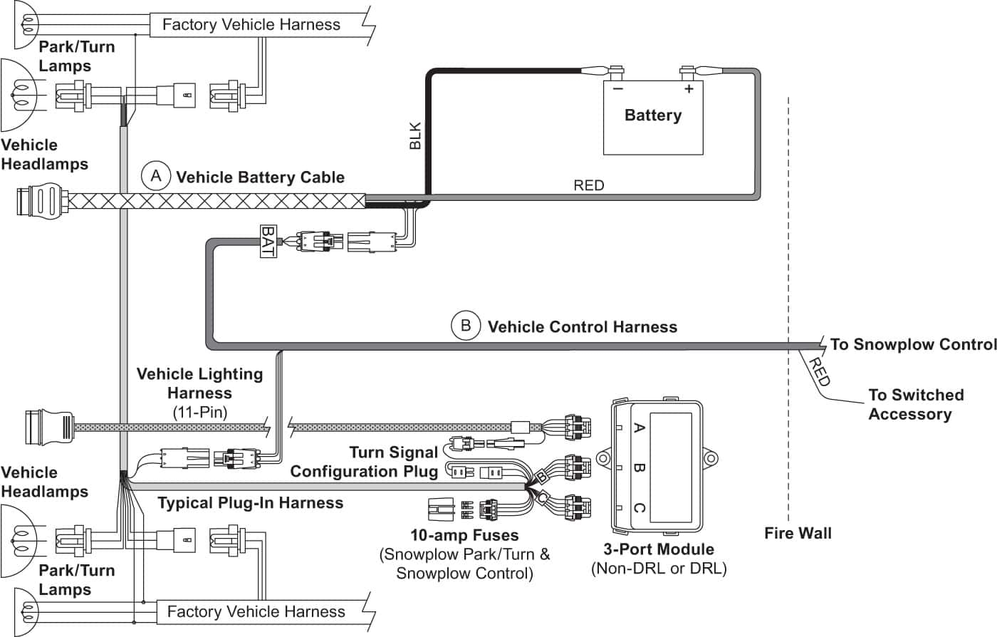
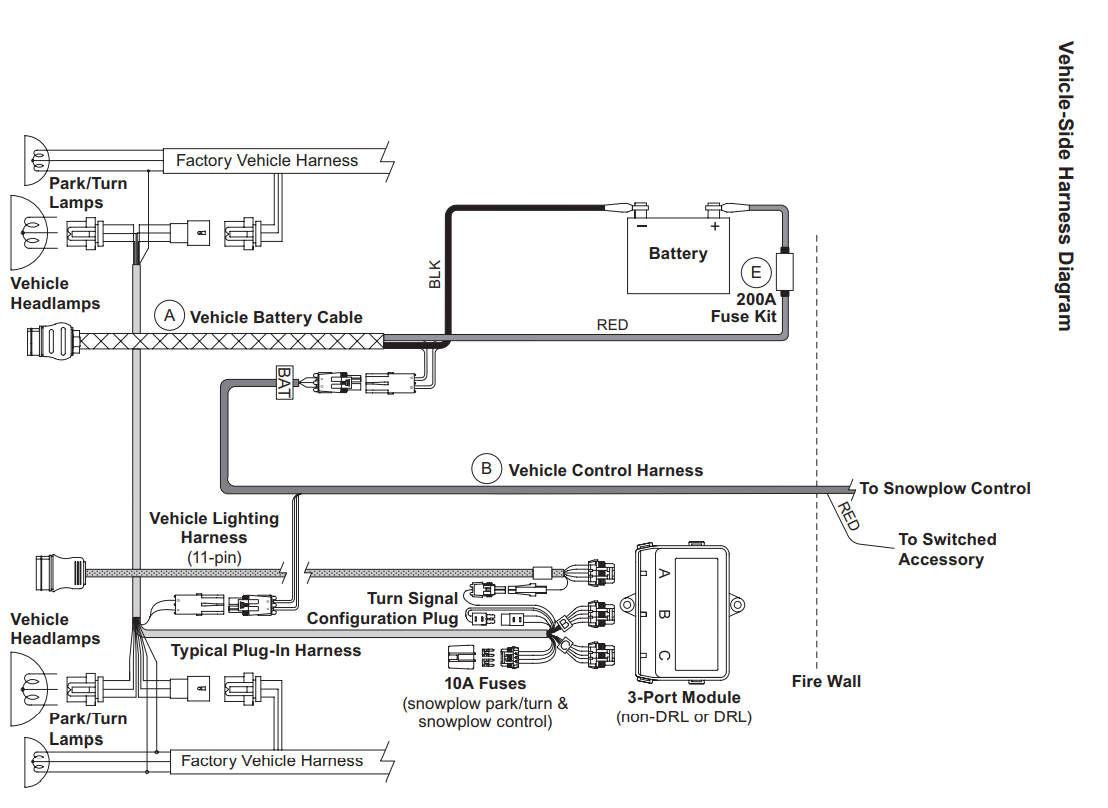
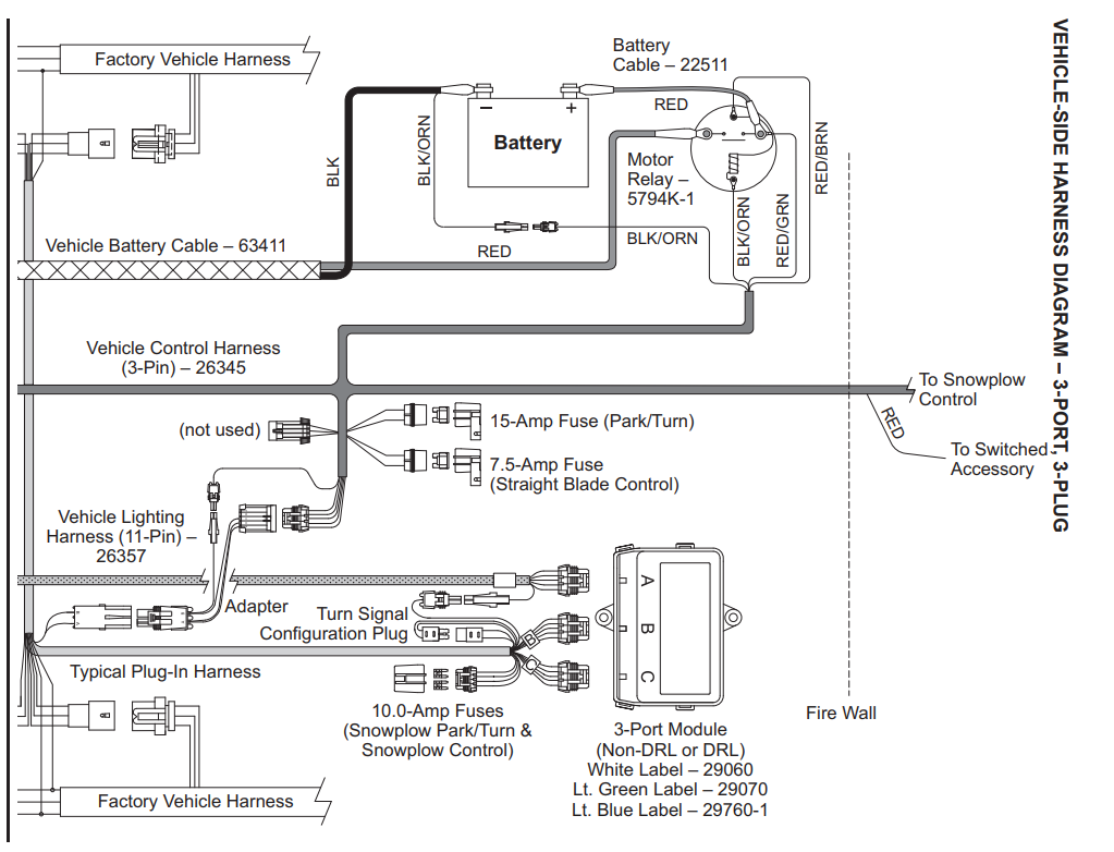
The Fisher Plow Minute Mount 2 Wiring Diagram provides a visual representation of the electrical connections between the various components of the plow system. Each wire is color-coded and labeled to indicate its function and corresponding connection point. By following the diagram carefully, you can easily identify any faults or discrepancies in the wiring and address them accordingly.
Troubleshooting Tips
- Use a multimeter to test the continuity and voltage of each wire in the system.
- Check for loose or corroded connections that may be disrupting the flow of electricity.
- Refer to the wiring diagram to ensure that each wire is connected to the correct terminal.
Installation Guide
- Begin by mounting the plow frame onto the vehicle according to the manufacturer’s instructions.
- Connect the control module and solenoid to their respective mounting points on the vehicle.
- Refer to the wiring diagram to make the necessary electrical connections between the components.
- Test the operation of the plow to ensure that all functions are working correctly.
Conclusion
In conclusion, the Fisher Plow Minute Mount 2 Wiring Diagram is an essential resource for anyone working with a Minute Mount 2 plow system. By understanding the components and connections outlined in the diagram, you can effectively troubleshoot issues, perform installations, and ensure the proper functioning of your plow. With this valuable tool at your disposal, you can tackle any electrical challenges with confidence and precision.
Related to Fisher Plow Minute Mount 2 Wiring Diagram
- Feniex 4200 Mini Wiring Diagram
- Fire Alarm Wiring Diagram
- Firing Order 5.7 Hemi Spark Plug Wiring Diagram
- Fisher Minute Mount 2 Wiring Diagram
- Fisher Plow Controller Wiring Diagram
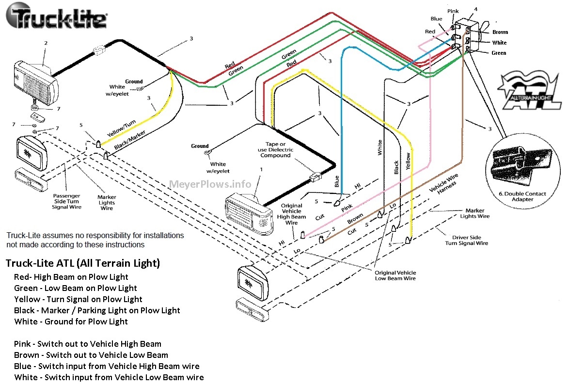
Smith Brothers Services Sealed Beam Plow Light Wiring Diagram
The image title is Smith Brothers Services Sealed Beam Plow Light Wiring Diagram, features dimensions of width 1174 px and height 796 px, with a file size of 1174 x 796 px. This image image/jpeg type visual are source from smithbrothersservices.com.
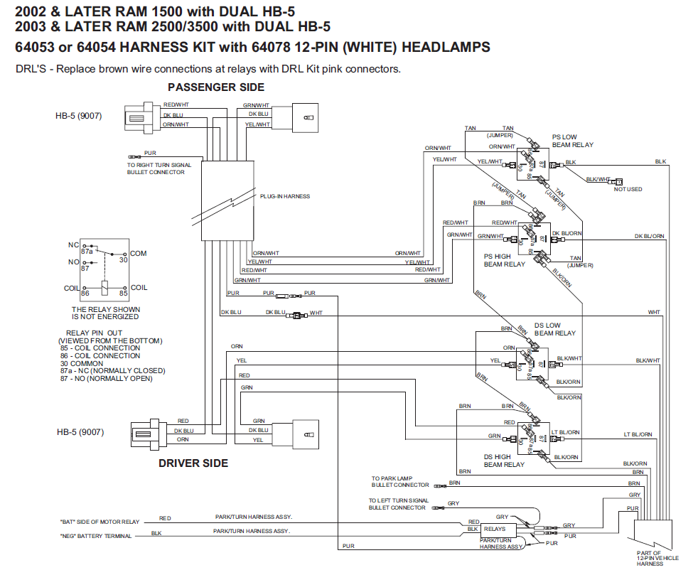
64053 Western Fisher Unimount 02 06 Dodge HB 5 12 Pin Control Wiring Harness 63427
The image title is 64053 Western Fisher Unimount 02 06 Dodge HB 5 12 Pin Control Wiring Harness 63427, features dimensions of width 975 px and height 809 px, with a file size of 975 x 809 px. This image image/png type visual are source from www.storksplows.com.
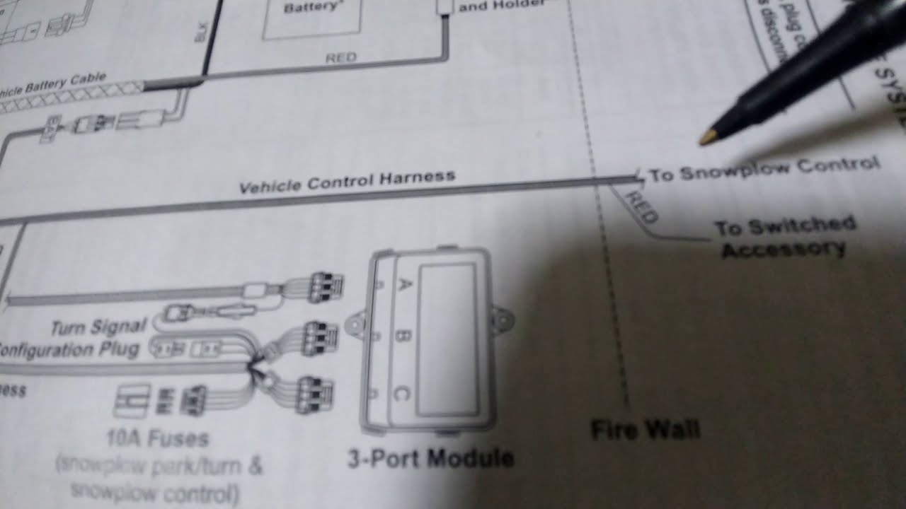
FisherPlow Wire Diagram 2 Plug With 3 Port Module System YouTube
The image title is FisherPlow Wire Diagram 2 Plug With 3 Port Module System YouTube, features dimensions of width 1280 px and height 720 px, with a file size of 1280 x 720. This image image/jpeg type visual are source from www.youtube.com.
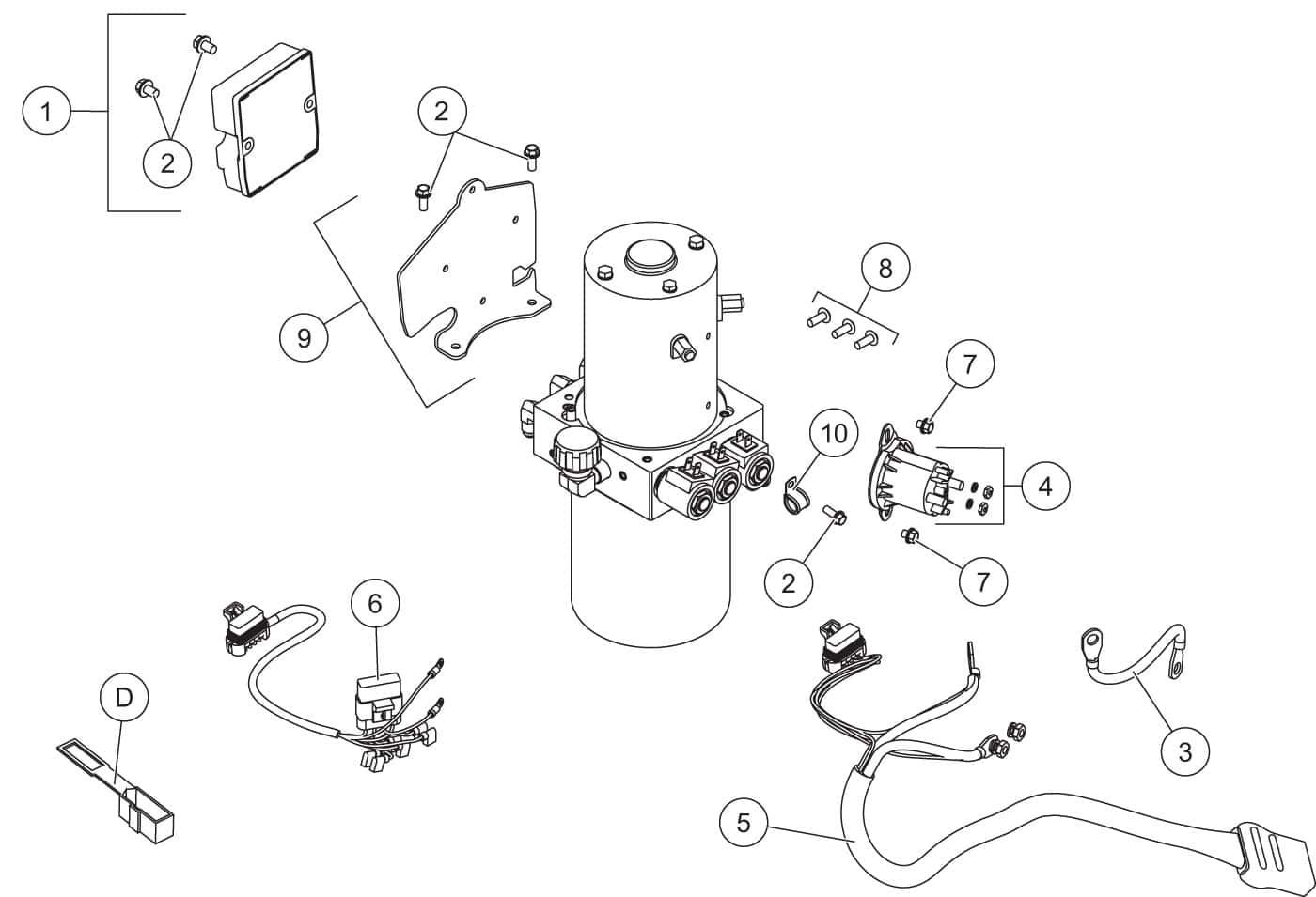
Fisher HD2 EC HD2 Electrical Components Shop ITEParts
The image title is Fisher HD2 EC HD2 Electrical Components Shop ITEParts, features dimensions of width 1400 px and height 955 px, with a file size of 1400 x 955. This image image/jpeg type visual are source from iteparts.com.
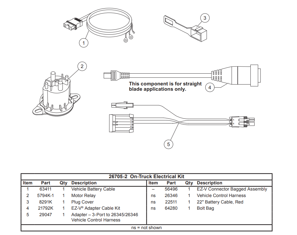
SHOP SNOWPLOW PARTS GENUINE FISHER SNOWPLOWS REPLACEMENT PARTS MINUTE MOUNT 2 PARTS MINUTE MOUNT 2 THREE PLUG PLOWS EZ V 8 1 2 9 1 2 EZ
The image title is SHOP SNOWPLOW PARTS GENUINE FISHER SNOWPLOWS REPLACEMENT PARTS MINUTE MOUNT 2 PARTS MINUTE MOUNT 2 THREE PLUG PLOWS EZ V 8 1 2 9 1 2 EZ, features dimensions of width 1007 px and height 798 px, with a file size of 1007 x 798. This image image/png type visual are source from www.fishersnowplowparts.com
Fisher XV2 V Plow Diagram Shop ITEParts
The image title is Fisher XV2 V Plow Diagram Shop ITEParts, features dimensions of width 1400 px and height 894 px, with a file size of 1400 x 894. This image image/jpeg type visual are source from iteparts.com.
SHOP SNOWPLOW PARTS GENUINE FISHER SNOWPLOWS REPLACEMENT PARTS MINUTE MOUNT 2 PARTS MINUTE MOUNT 2 FLEET FLEX PLOW PARTS 8 1 2 9 1 2 EXTREME V SNOW
The image title is SHOP SNOWPLOW PARTS GENUINE FISHER SNOWPLOWS REPLACEMENT PARTS MINUTE MOUNT 2 PARTS MINUTE MOUNT 2 FLEET FLEX PLOW PARTS 8 1 2 9 1 2 EXTREME V SNOW, features dimensions of width 1108 px and height 808 px, with a file size of 1108 x 808. This image image/png type visual are source from www.fishersnowplowparts.com.
SHOP SNOWPLOW PARTS GENUINE FISHER SNOWPLOWS REPLACEMENT PARTS MINUTE MOUNT 2 PARTS MINUTE MOUNT 2 THREE PLUG PLOWS STRAIGHT PLOWS TRUCK SIDE COMMON WIRING ASH SUPPLY COMPANY LLC
The image title is SHOP SNOWPLOW PARTS GENUINE FISHER SNOWPLOWS REPLACEMENT PARTS MINUTE MOUNT 2 PARTS MINUTE MOUNT 2 THREE PLUG PLOWS STRAIGHT PLOWS TRUCK SIDE COMMON WIRING ASH SUPPLY COMPANY LLC, features dimensions of width 1023 px and height 782 px, with a file size of 1023 x 782.
The images on this page, sourced from Google for educational purposes, may be copyrighted. If you own an image and wish its removal or have copyright concerns, please contact us. We aim to promptly address these issues in compliance with our copyright policy and DMCA standards. Your cooperation is appreciated.
Related Keywords to Fisher Plow Minute Mount 2 Wiring Diagram:
fisher minute mount 2 plow not working,fisher minute mount 2 v plow wiring diagram,fisher minute mount 2 wiring diagram plow side,fisher plow minute mount 2 wiring diagram,how to wire a fisher minute mount plow
