Table of Contents
Exploring the Value of Brake Light Switch Wiring Diagram
Exploring the Value of Brake Light Switch Wiring Diagram
When it comes to the safety of vehicles, the brake system plays a crucial role in ensuring smooth and secure driving experiences. One vital component of this system is the brake light switch, which activates the brake lights when the pedal is pressed, alerting other drivers of your intention to slow down or stop. Understanding the intricacies of brake light switch wiring is essential for maintaining the functionality of this critical safety feature. A comprehensive brake light switch wiring diagram not only provides valuable insights into the wiring connections but also serves as a guide for troubleshooting and repairs. Let’s delve into the world of brake light switch wiring diagrams to unravel their significance and practical applications.
The Basics of Brake Light Switch Wiring Diagram
A brake light switch wiring diagram is a visual representation of the electrical connections involved in the operation of the brake light switch. It illustrates how the switch is connected to the vehicle’s electrical system, including the brake lights, battery, and other relevant components. By studying this diagram, automotive enthusiasts and professionals can gain a deeper understanding of how the brake light switch functions and how to diagnose and fix potential issues effectively.
Key Components of a Brake Light Switch Wiring Diagram
The primary components depicted in a brake light switch wiring diagram include the brake light switch itself, wires connecting the switch to the brake lights, and the power source (typically the vehicle’s battery). Additionally, the diagram may indicate other elements such as fuses, relays, and connectors that play a role in the overall functionality of the brake light system. Each component’s position and connection points are clearly illustrated, providing a comprehensive overview of the wiring setup.
Benefits of Using a Brake Light Switch Wiring Diagram
Enhanced Understanding: Visual representation aids in grasping complex wiring configurations.
Troubleshooting Assistance: Helps identify and rectify wiring issues efficiently.
Repair Guidance: Serves as a roadmap for conducting repairs and replacements accurately.
How to Interpret a Brake Light Switch Wiring Diagram
Interpreting a brake light switch wiring diagram requires a basic understanding of electrical circuits and wiring principles. By following the lines and symbols on the diagram, individuals can trace the path of electrical current flow and identify potential points of failure or malfunction. Here are some essential steps to effectively interpret a brake light switch wiring diagram:
Identify the Components: Familiarize yourself with the symbols representing different electrical components.
Follow the Wiring Paths: Trace the lines connecting various components to understand the circuitry.
Check for Continuity: Use a multimeter to check for continuity in wires and connections.
Troubleshoot Systematically: Methodically diagnose and address any wiring issues or faults.
Conclusion
In conclusion, a brake light switch wiring diagram is a valuable tool for anyone involved in vehicle maintenance, repair, or modification. By studying and interpreting these diagrams, individuals can gain insights into the intricate wiring systems of brake light switches and ensure the safety and functionality of their vehicles. Whether you are a DIY enthusiast or a professional mechanic, understanding the nuances of brake light switch wiring diagrams can enhance your ability to address electrical issues effectively. Make sure to consult these diagrams whenever you encounter brake light system problems to streamline your diagnostic and repair processes.
Related to Brake Light Switch Wiring Diagram
- Boss Plow Wiring Diagram
- Boss Radio Wiring Diagram
- Boss Snow Plow Wiring Diagram
- Braeburn Thermostat Wiring Diagram
- Brake Controller Wiring Diagram
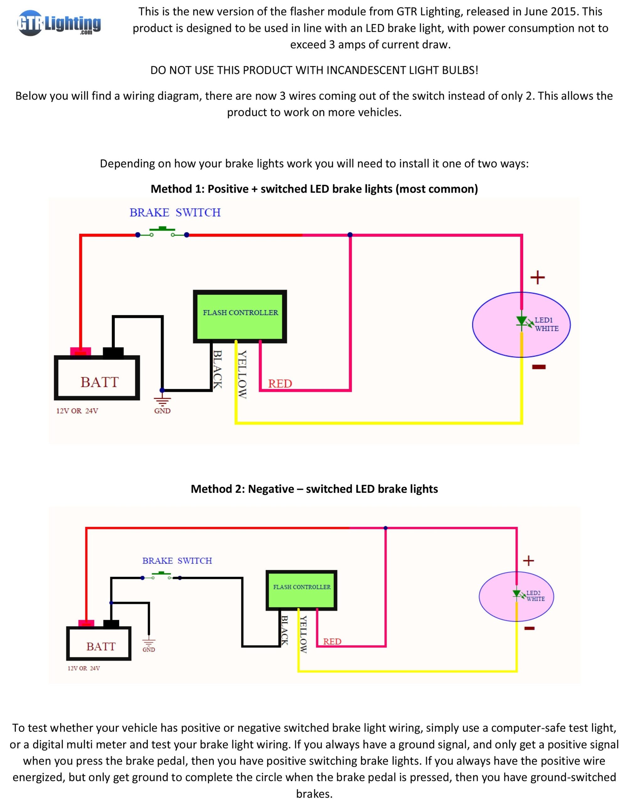
HOW TO INSTALL A 3RD BRAKE LIGHT FLASHER
The image title is HOW TO INSTALL A 3RD BRAKE LIGHT FLASHER, features dimensions of width 2033 px and height 2560 px, with a file size of 2339 x 2945 px. This image image/jpeg type visual are source from blog.headlightrevolution.com.
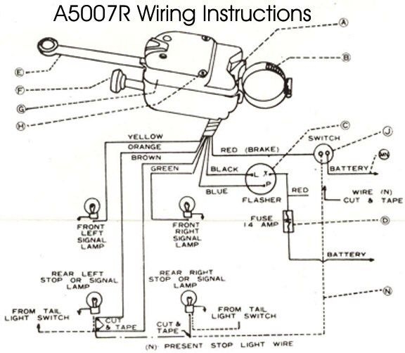
Wiring Diagram Universal Turn Signal Wiring Diagram Brake Light Universal Turn Electrical Circuit Diagram Basic Electronic Circuits Electrical Wiring Diagram
The image title is Wiring Diagram Universal Turn Signal Wiring Diagram Brake Light Universal Turn Electrical Circuit Diagram Basic Electronic Circuits Electrical Wiring Diagram, features dimensions of width 576 px and height 502 px, with a file size of 576 x 502 px. This image image/jpeg type visual are source from www.pinterest.com.
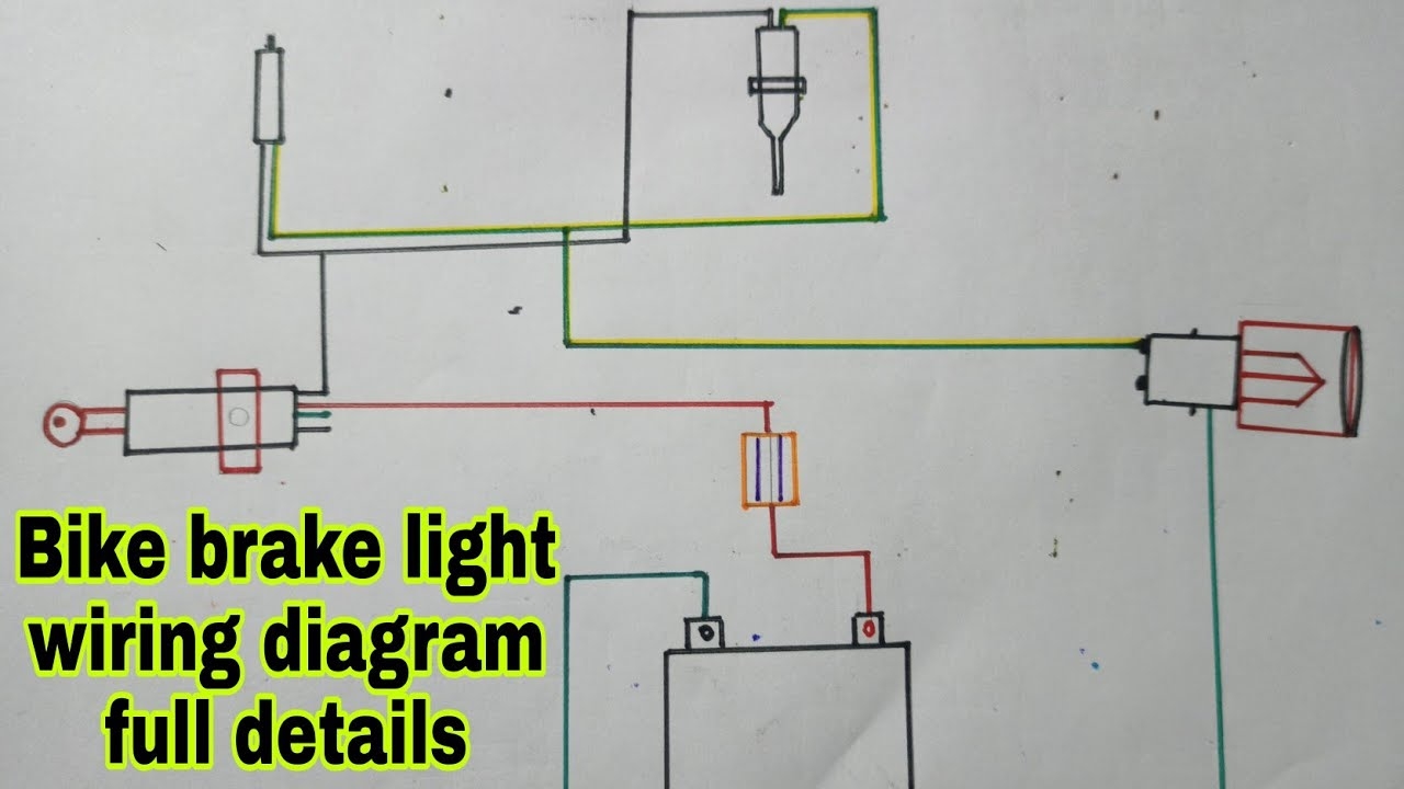
All Bike Brake Light Wiring Diagram Full Details YouTube
The image title is All Bike Brake Light Wiring Diagram Full Details YouTube, features dimensions of width 1280 px and height 720 px, with a file size of 1280 x 720. This image image/jpeg type visual are source from m.youtube.com.
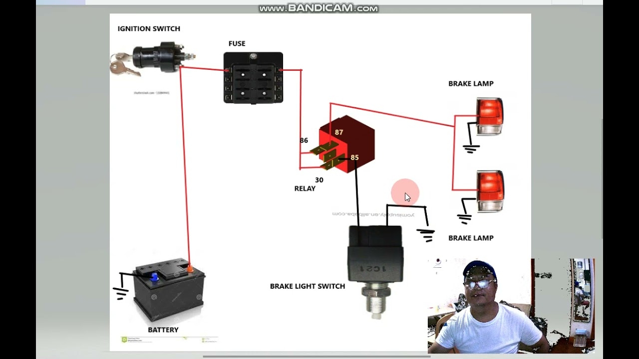
BRAKE LIGHT WIRING DIAGRAM YouTube
The image title is BRAKE LIGHT WIRING DIAGRAM YouTube, features dimensions of width 1280 px and height 720 px, with a file size of 1280 x 720. This image image/jpeg type visual are source from m.youtube.com.
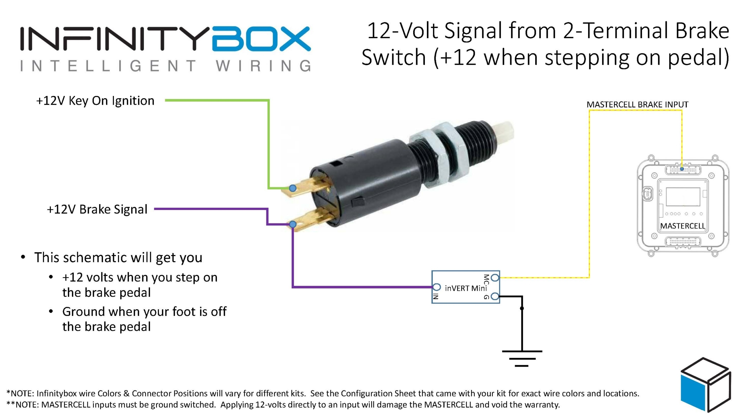
12 Volt Brake Light Signals Infinitybox
The image title is 12 Volt Brake Light Signals Infinitybox, features dimensions of width 2560 px and height 1440 px, with a file size of 2560 x 1440. This image image/jpeg type visual are source from www.infinitybox.com
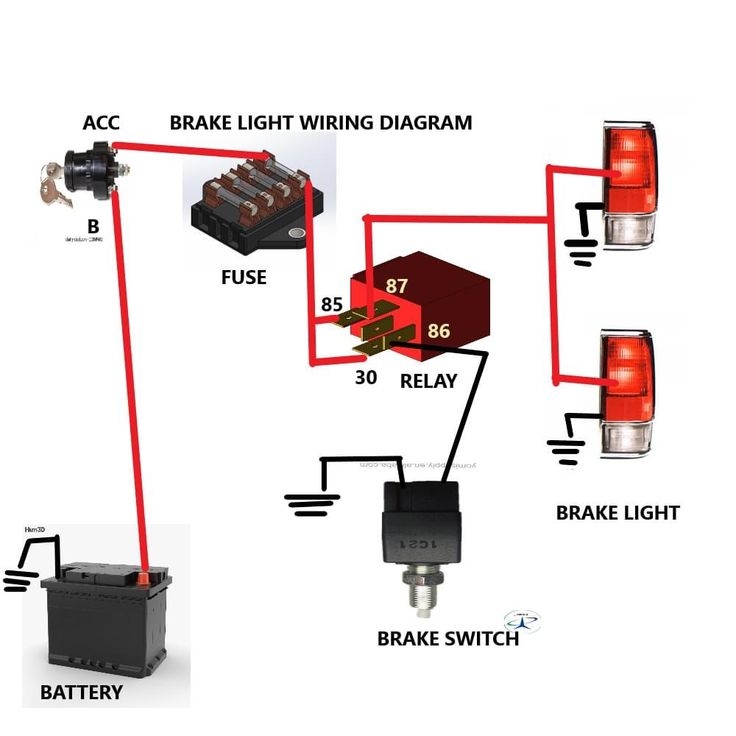
Brake Light Wiring Diagram Car Alternator Trailer Light Wiring
The image title is Brake Light Wiring Diagram Car Alternator Trailer Light Wiring, features dimensions of width 736 px and height 736 px, with a file size of 736 x 736. This image image/jpeg type visual are source from www.pinterest.com.
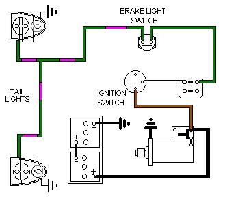
Brake Lights
The image title is Brake Lights, features dimensions of width 332 px and height 294 px, with a file size of 332 x 294. This image image/jpeg type visual are source from www.mgb-stuff.org.uk.
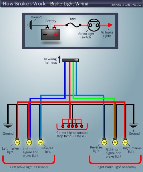
How Brake Light Wiring Works Trailer Light Wiring Led Trailer Lights Tail Light
The image title is How Brake Light Wiring Works Trailer Light Wiring Led Trailer Lights Tail Light, features dimensions of width 500 px and height 600 px, with a file size of 500 x 600.
The images on this page, sourced from Google for educational purposes, may be copyrighted. If you own an image and wish its removal or have copyright concerns, please contact us. We aim to promptly address these issues in compliance with our copyright policy and DMCA standards. Your cooperation is appreciated.
Related Keywords to Brake Light Switch Wiring Diagram:
brake light pressure switch wiring diagram,brake light switch wiring diagram,brake pedal switch wiring diagram,e46 brake light switch wiring diagram,gm brake light switch wiring diagram
