Table of Contents
The Ultimate Guide to Boss Plow Wiring Diagram
The Ultimate Guide to Boss Plow Wiring Diagram
When it comes to installing and maintaining your Boss plow, having a comprehensive wiring diagram is essential. The Boss plow wiring diagram serves as a roadmap for connecting all the electrical components of your plow system, ensuring proper functionality and safety. Whether you’re a seasoned mechanic or a DIY enthusiast, understanding the wiring diagram is crucial for troubleshooting issues, upgrading components, or simply getting your plow ready for the winter season. In this guide, we’ll delve into the intricacies of Boss plow wiring diagrams, providing you with valuable insights and tips to navigate your way through this critical aspect of plow maintenance.
The Importance of Boss Plow Wiring Diagram
The wiring diagram for your Boss plow is like a blueprint that guides you through the intricate network of wires, switches, relays, and connectors that make up the electrical system. Without a clear understanding of how these components are interconnected, troubleshooting electrical issues can be a daunting task. By referring to the wiring diagram, you can quickly identify the source of a problem, trace the flow of electricity, and make informed decisions on repairs or replacements. Whether you’re installing a new plow or troubleshooting an existing one, having access to a detailed wiring diagram can save you time, money, and frustration.
Key Components of Boss Plow Wiring Diagram
A typical Boss plow wiring diagram consists of several key components that are essential for understanding the electrical system. These components include:
Control Module: The brain of the plow system that manages the operation of various functions.
Power Cable: Connects the plow to the vehicle’s battery to provide electrical power.
Solenoid: Controls the flow of power to the plow motor and other components.
Toggle Switches: Allows the operator to control the movement of the plow blade.
Relays: Act as electrical switches that control high-current circuits.
Understanding Boss Plow Wiring Diagram Symbols
To interpret a Boss plow wiring diagram effectively, you need to familiarize yourself with the symbols used to represent different electrical components. Some common symbols you may encounter include:
Lines: Represent electrical wires that connect various components.
Circles: Indicate connections or junction points where wires meet.
Squares: Denote switches or relays that control the flow of electricity.
Arrows: Show the direction of current flow within the circuit.
Tips for Using Boss Plow Wiring Diagram
To make the most of your Boss plow wiring diagram, consider the following tips:
Label Wires: Before starting any wiring work, label each wire with its corresponding function to avoid confusion.
Use Color Codes: Follow the color-coding specified in the wiring diagram to ensure proper connections.
Double-Check Connections: Verify each connection against the diagram to prevent errors that could lead to electrical issues.
Seek Professional Help: If you’re unsure about any aspect of the wiring process, don’t hesitate to consult a professional or contact Boss technical support for guidance.
Related to Boss Plow Wiring Diagram
- Bose Factory Amp Wiring Diagram
- Boss 13 Pin Wiring Harness Diagram
- Boss Audio System Wiring Diagram
- Boss Audio Wiring Diagram
- Boss Plow Solenoid Wiring Diagram
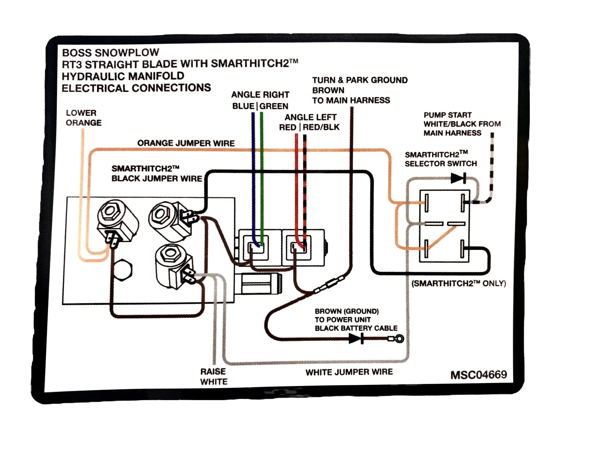
Professional Parts Wholesale Hard Working Parts For Hard Working People MSC04669 Boss Straight Blade SH2 Hydraulic Manifold Electrical Decal OEM
The image title is Professional Parts Wholesale Hard Working Parts For Hard Working People MSC04669 Boss Straight Blade SH2 Hydraulic Manifold Electrical Decal OEM, features dimensions of width 2016 px and height 1511 px, with a file size of 2016 x 1511 px. This image image/jpeg type visual are source from professionalparts.com.
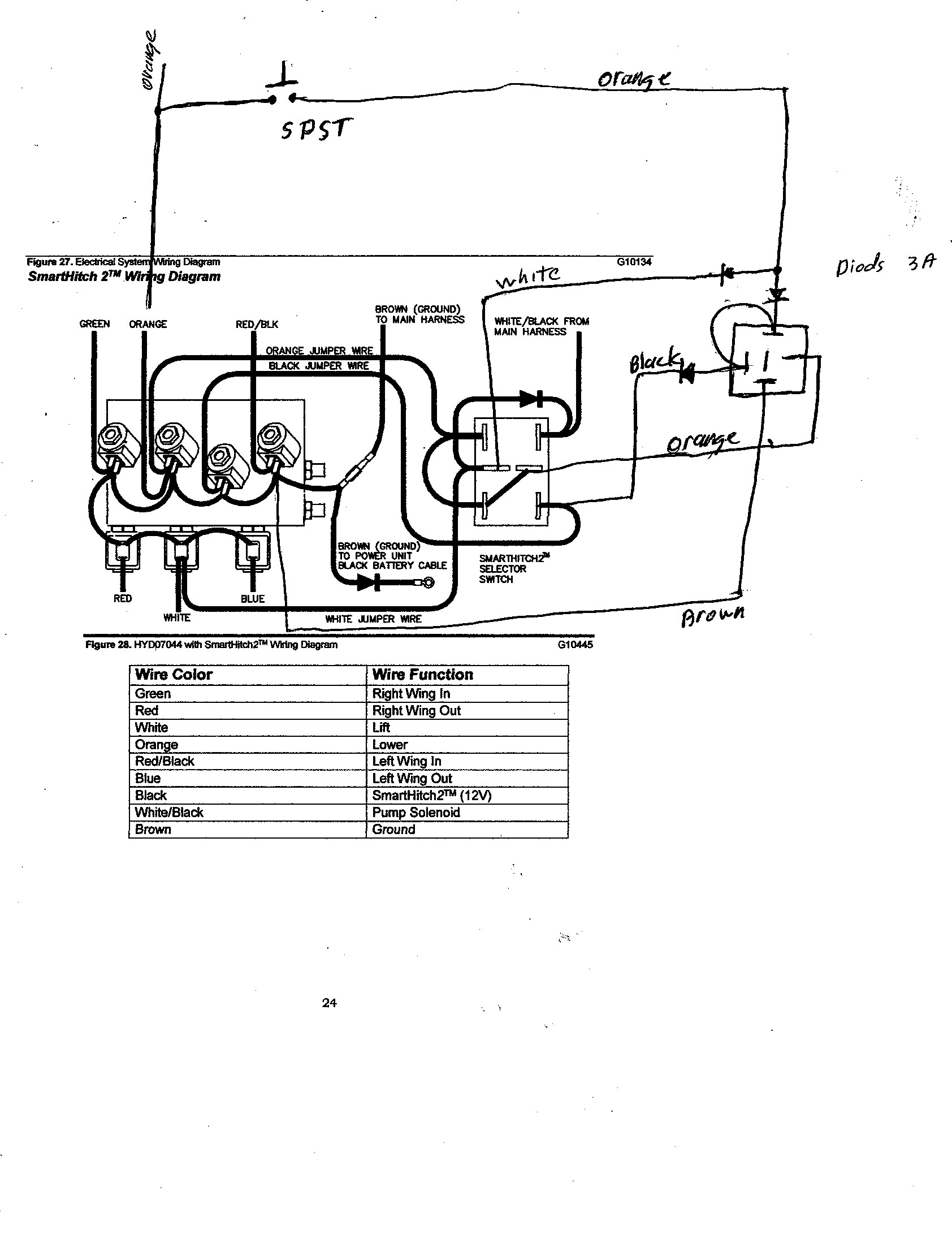
Boss Snow Plow D Force Snow Plowing Forum
The image title is Boss Snow Plow D Force Snow Plowing Forum, features dimensions of width 1684 px and height 2184 px, with a file size of 1684 x 2184 px. This image image/jpeg type visual are source from www.plowsite.com.
BOSS Straight Blade Parts Diagram From ITEParts
The image title is BOSS Straight Blade Parts Diagram From ITEParts, features dimensions of width 2015 px and height 1883 px, with a file size of 2015 x 1883. This image image/png type visual are source from iteparts.com.
Professional Parts Wholesale Hard Working Parts For Hard Working People MSC04668 Boss V Blade SH2 Hydraulic Manifold Electrical Decal OEM
The image title is Professional Parts Wholesale Hard Working Parts For Hard Working People MSC04668 Boss V Blade SH2 Hydraulic Manifold Electrical Decal OEM, features dimensions of width 2560 px and height 1919 px, with a file size of 4032 x 3023. This image image/jpeg type visual are source from professionalparts.com.
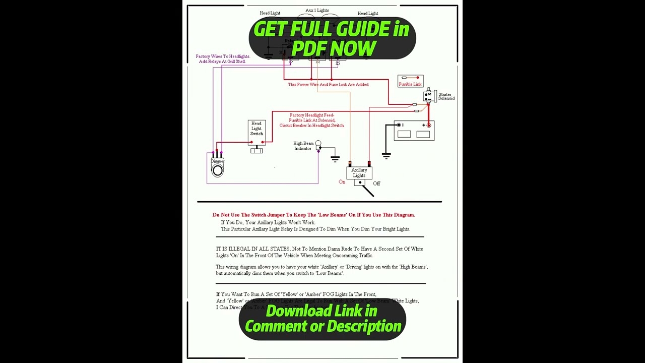
DIAGRAM Boss Plow Solenoid Wiring Diagram YouTube
The image title is DIAGRAM Boss Plow Solenoid Wiring Diagram YouTube, features dimensions of width 1280 px and height 720 px, with a file size of 1280 x 720. This image image/jpeg type visual are source from www.youtube.com
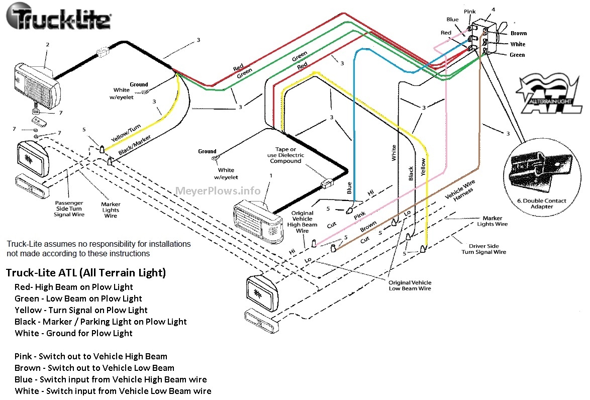
Smith Brothers Services Sealed Beam Plow Light Wiring Diagram
The image title is Smith Brothers Services Sealed Beam Plow Light Wiring Diagram, features dimensions of width 1174 px and height 796 px, with a file size of 1174 x 796. This image image/jpeg type visual are source from smithbrothersservices.com.
BOSS Power V And Power V XT Parts Diagram From ITEParts
The image title is BOSS Power V And Power V XT Parts Diagram From ITEParts, features dimensions of width 2007 px and height 2102 px, with a file size of 2007 x 2102. This image image/png type visual are source from iteparts.com.
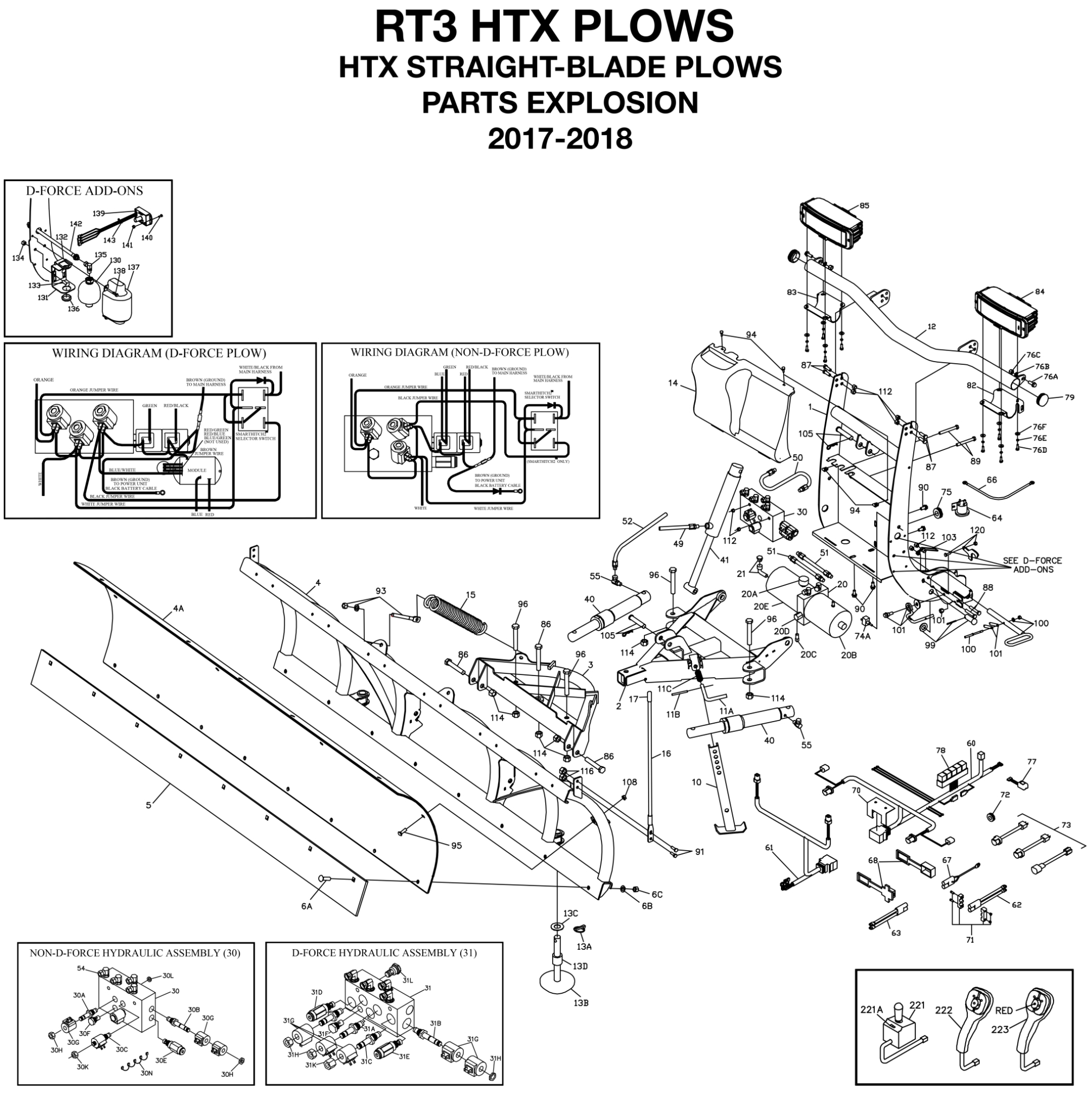
BOSS RT3 HTX Straight Blade Parts Diagram From ITEParts
The image title is BOSS RT3 HTX Straight Blade Parts Diagram From ITEParts, features dimensions of width 2015 px and height 2016 px, with a file size of 2015 x 2016.
The images on this page, sourced from Google for educational purposes, may be copyrighted. If you own an image and wish its removal or have copyright concerns, please contact us. We aim to promptly address these issues in compliance with our copyright policy and DMCA standards. Your cooperation is appreciated.
Related Keywords to Boss Plow Wiring Diagram:
boss plow wiring diagram,boss plow wiring diagram chevy,boss plow wiring diagram chevy silverado,boss plow wiring diagram gmc,boss snowplow wiring diagram
