Table of Contents
Unlocking the Potential of 3 Wire Speed Sensor Wiring Diagram
The Power of 3 Wire Speed Sensor Wiring Diagram
When it comes to understanding the intricate workings of your vehicle’s speed sensor, having a comprehensive wiring diagram at your disposal can prove to be a game-changer. Among the various types of speed sensors, the 3 wire speed sensor stands out for its efficiency and accuracy in measuring speed. By delving into the world of 3 wire speed sensor wiring diagrams, you unlock a wealth of knowledge that can enhance your understanding of how your vehicle operates and pave the way for smoother maintenance and troubleshooting processes.
Understanding the Basics
Before diving into the specifics of a 3 wire speed sensor wiring diagram, it’s essential to grasp the basics of how these sensors function. The primary role of a speed sensor is to monitor the rotational speed of a component, such as a wheel or transmission shaft, and send this data to the vehicle’s control system. With a 3 wire configuration, these sensors typically consist of power, ground, and signal wires, each playing a crucial role in ensuring accurate speed detection.
Key Components
Within the realm of 3 wire speed sensor wiring diagrams, understanding the purpose of each wire is paramount. The power wire supplies the necessary voltage for the sensor to operate, while the ground wire serves as the return path for current flow. The signal wire, often referred to as the output wire, carries the speed data collected by the sensor to the vehicle’s control unit for processing.
Installation and Troubleshooting
Whether you’re installing a new 3 wire speed sensor or troubleshooting an existing one, having a detailed wiring diagram can simplify the process significantly. By following the wiring layout provided in the diagram, you can ensure proper connections and avoid common pitfalls that may arise during installation. In case of troubleshooting issues, the diagram serves as a valuable tool for pinpointing potential wiring faults and rectifying them swiftly.
Benefits of Using a Wiring Diagram
The advantages of utilizing a 3 wire speed sensor wiring diagram extend beyond mere installation and troubleshooting tasks. By studying the diagram closely, you gain insights into the intricate interplay between the sensor and other vehicle components, enabling you to make informed decisions regarding maintenance and repairs. Additionally, a well-documented wiring diagram can serve as a reference guide for future endeavors, saving you time and effort in the long run.
Related to 3 Wire Speed Sensor Wiring Diagram
- 3 Wire Rtd Wiring Diagram
- 3 Wire Security Camera Wiring Diagram
- 3 Wire Smoke Detector Wiring Diagram
- 3 Wire Solenoid Valve Wiring Diagram
- 3 Wire Solenoid Wiring Diagram
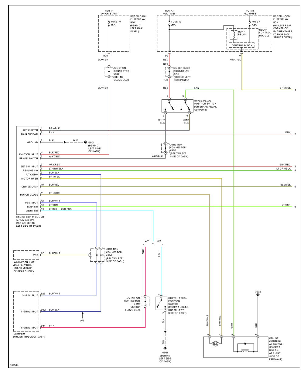
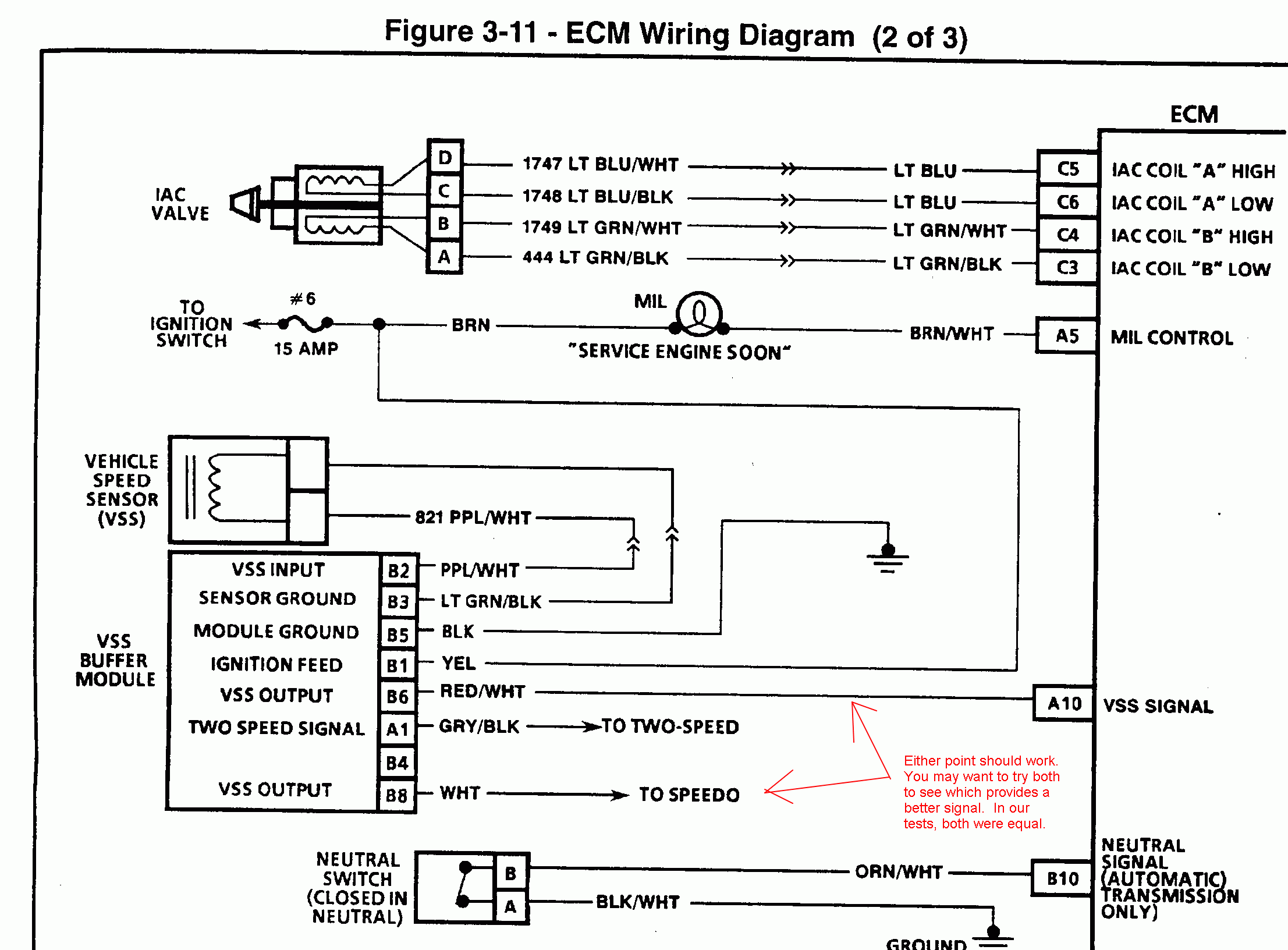
Reading Vehicle Speed Sensor On 2005 Honda Accord From Cruise Control Unit Port Motor Vehicle Maintenance Repair Stack Exchange
The image title is Reading Vehicle Speed Sensor On 2005 Honda Accord From Cruise Control Unit Port Motor Vehicle Maintenance Repair Stack Exchange, features dimensions of width 1001 px and height 1234 px, with a file size of 1001 x 1234 px. This image image/png type visual are source from mechanics.stackexchange.com.
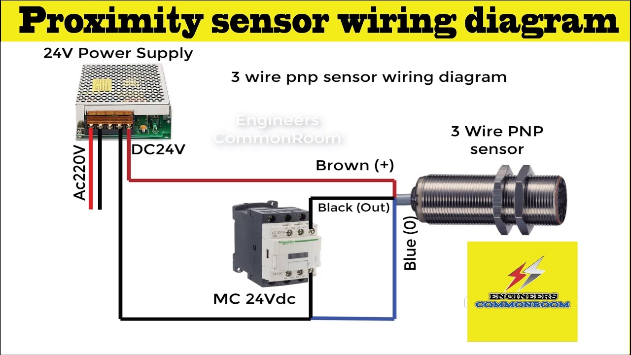
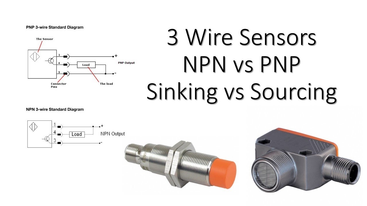
3 Wire Proximity Sensor Wiring Diagram Engineers CommonRoom Electrical Circuit Diagram YouTube
The image title is 3 Wire Proximity Sensor Wiring Diagram Engineers CommonRoom Electrical Circuit Diagram YouTube, features dimensions of width 1280 px and height 720 px, with a file size of 1280 x 720 px. This image image/jpeg type visual are source from www.youtube.com.
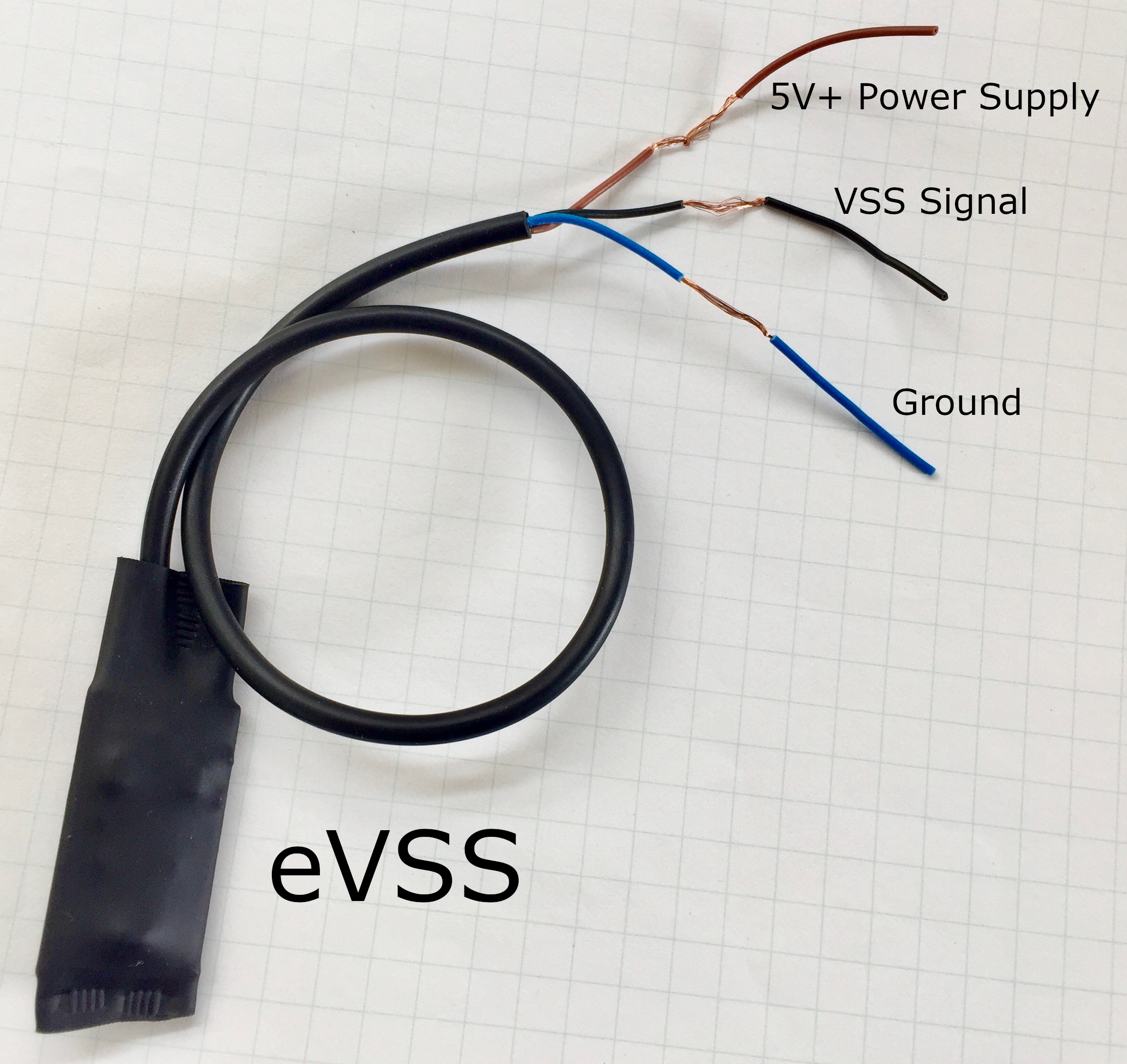
Vehicle Speed Sensor Install
The image title is Vehicle Speed Sensor Install, features dimensions of width 2371 px and height 2239 px, with a file size of 2371 x 2239. This image image/jpeg type visual are source from www.busaru.com.
Solution Swap With 3 Wire VSS LS1TECH Camaro And Firebird Forum Discussion
The image title is Solution Swap With 3 Wire VSS LS1TECH Camaro And Firebird Forum Discussion, features dimensions of width 445 px and height 451 px, with a file size of 445 x 451. This image image/png type visual are source from ls1tech.com.
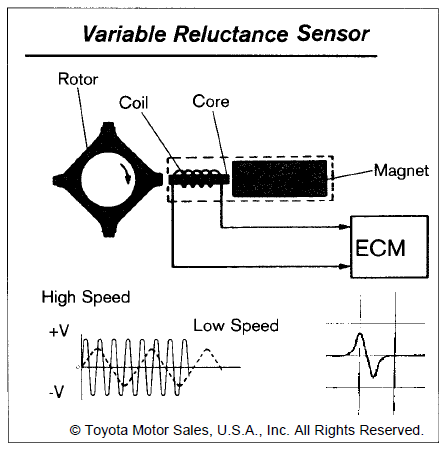
2 Wire And 3 Speed Sensor Sender ClubLexus Lexus Forum Discussion
The image title is 2 Wire And 3 Speed Sensor Sender ClubLexus Lexus Forum Discussion, features dimensions of width 2213 px and height 1632 px, with a file size of 2213 x 1632. This image image/gif type visual are source from www.clublexus.com
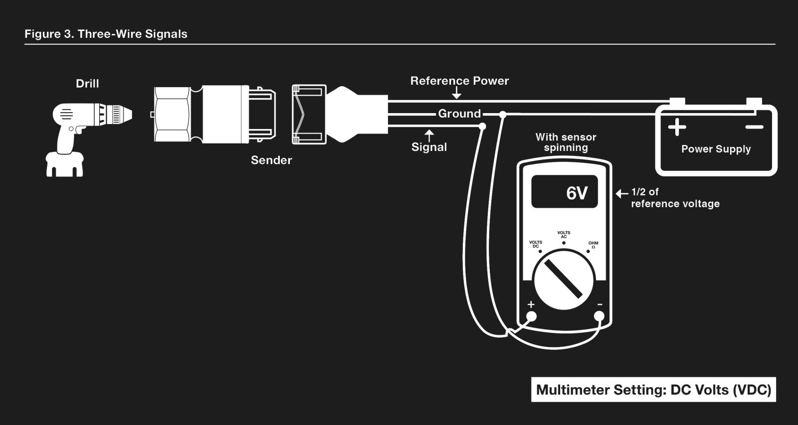
Testing Speedometer Signals
The image title is Testing Speedometer Signals, features dimensions of width 1600 px and height 853 px, with a file size of 1600 x 853. This image image/jpeg type visual are source from classicinstruments.com.
How To Wire A 3 Wire Sensor YouTube
The image title is How To Wire A 3 Wire Sensor YouTube, features dimensions of width 1280 px and height 720 px, with a file size of 1280 x 720. This image image/jpeg type visual are source from m.youtube.com.
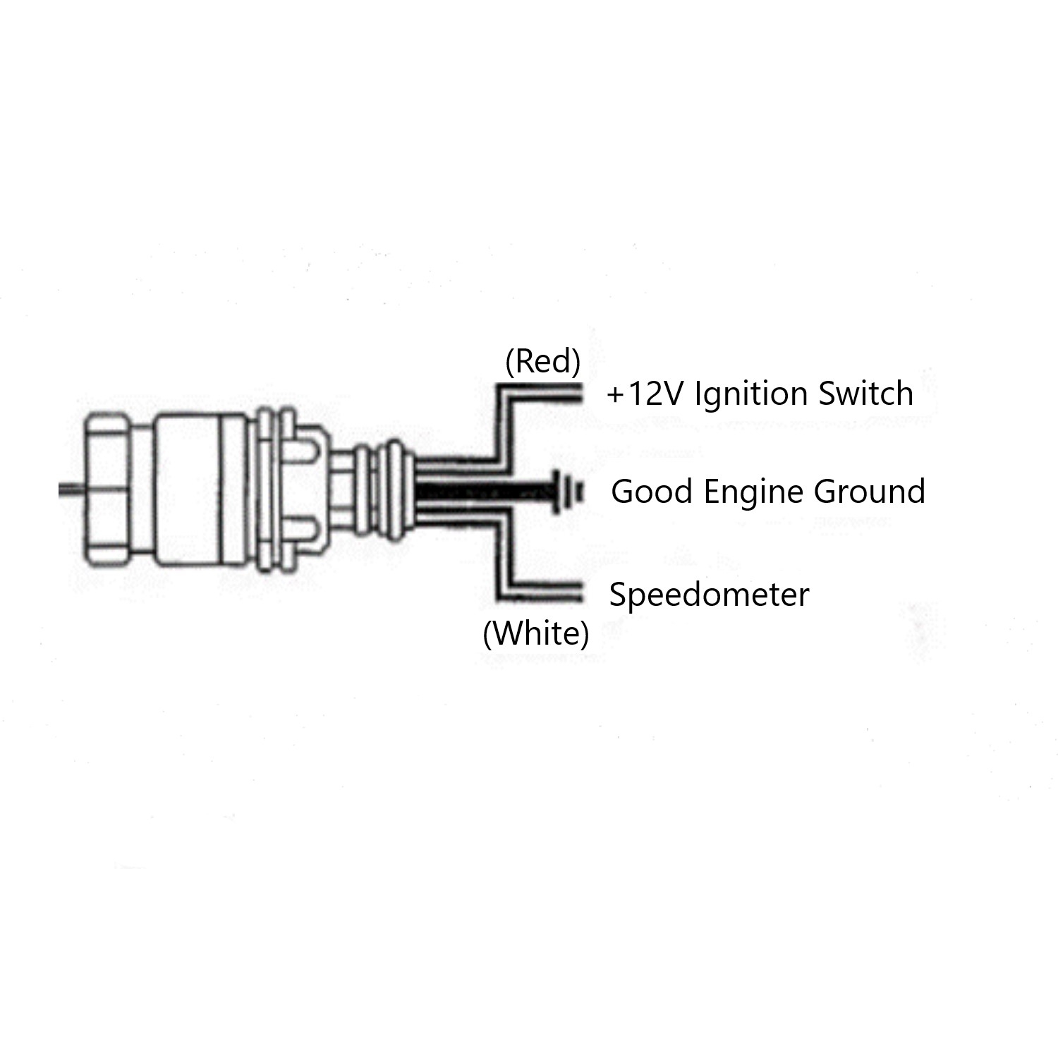
3 Wire Speed Sensor Hall Effect Sensor 82623B Stewart Warner
The image title is 3 Wire Speed Sensor Hall Effect Sensor 82623B Stewart Warner, features dimensions of width 1500 px and height 1500 px, with a file size of 1500 x 1500.
The images on this page, sourced from Google for educational purposes, may be copyrighted. If you own an image and wish its removal or have copyright concerns, please contact us. We aim to promptly address these issues in compliance with our copyright policy and DMCA standards. Your cooperation is appreciated.
Related Keywords to 3 Wire Speed Sensor Wiring Diagram:
2 wire vs 3 wire speed sensor,3 wire speed sensor wiring diagram,how does a 3 wire speed sensor work,how to wire a 2 wire speed sensor,toyota 3 wire speed sensor wiring diagram
