Table of Contents
Exploring the Value of 3 Wire Solenoid Wiring Diagram
The Value of 3 Wire Solenoid Wiring Diagram
When it comes to electrical systems, having a clear understanding of the wiring diagram is crucial for ensuring proper installation and functionality. In the world of solenoids, a 3 wire solenoid wiring diagram serves as a valuable tool that simplifies the complex process of connecting various components. This guide not only streamlines the installation process but also enhances the efficiency and effectiveness of the system. Let’s delve into the realm of 3 wire solenoid wiring diagrams to uncover the key insights and benefits they offer.
The Basics of a 3 Wire Solenoid Wiring Diagram
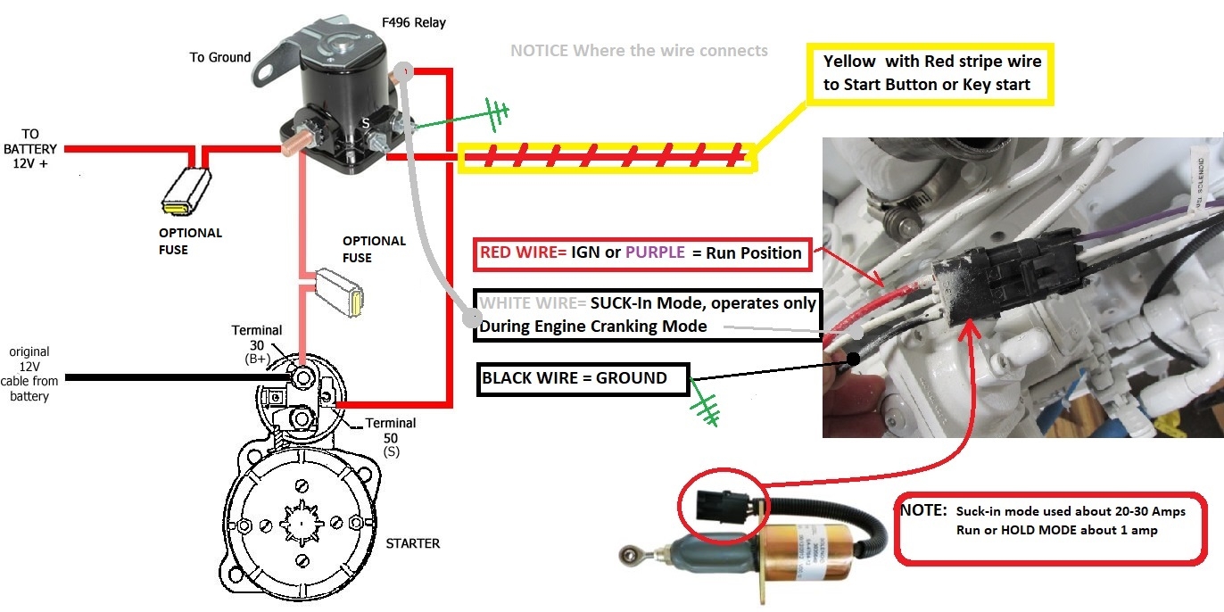
A 3 wire solenoid wiring diagram outlines the connections required for a solenoid with three distinct wires. These wires play crucial roles in controlling the operation of the solenoid, dictating factors such as power input, signal transmission, and grounding. By following the diagram meticulously, individuals can ensure that each wire is correctly connected to its designated terminal, preventing any potential issues or malfunctions.
Key Components
Power wire: Carries the electrical current to energize the solenoid
Signal wire: Transmits the control signal to activate the solenoid
Ground wire: Provides a path for the current to return after completing its circuit
Benefits of Using a 3 Wire Solenoid Wiring Diagram
The utilization of a 3 wire solenoid wiring diagram offers a multitude of advantages, ranging from simplifying the installation process to enhancing overall system performance. Some of the key benefits include:
Simplified Installation
By following a clear and concise wiring diagram, individuals can easily connect the necessary wires without confusion or errors. This streamlines the installation process, saving time and effort while ensuring accuracy in wiring configuration.
Optimized Functionality
A well-executed wiring diagram ensures that the solenoid operates at its full potential, maximizing efficiency and performance. Proper wiring connections prevent issues such as short circuits or voltage spikes, thereby prolonging the lifespan of the solenoid.
Troubleshooting Made Easy
In the event of any malfunctions or irregularities, having a detailed wiring diagram at hand simplifies the troubleshooting process. By referencing the diagram, individuals can quickly identify and rectify any wiring errors or faults, restoring the solenoid to its optimal condition.
Conclusion
In conclusion, a 3 wire solenoid wiring diagram is a valuable resource that offers clarity, convenience, and efficiency in connecting solenoid components. By understanding the basics of the diagram and harnessing its benefits, individuals can elevate the performance and reliability of their electrical systems. Whether for professional installations or DIY projects, the guidance provided by a wiring diagram is indispensable in achieving seamless operation and longevity for solenoids.
Related to 3 Wire Solenoid Wiring Diagram
- 3 Wire Proximity Sensor Wiring Diagram
- 3 Wire Rtd Wiring Diagram
- 3 Wire Security Camera Wiring Diagram
- 3 Wire Smoke Detector Wiring Diagram
- 3 Wire Solenoid Valve Wiring Diagram
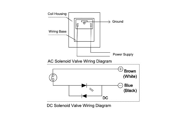
FAQ ATO Solenoid Valves
The image title is FAQ ATO Solenoid Valves, features dimensions of width 587 px and height 371 px, with a file size of 587 x 371 px. This image image/jpeg type visual are source from www.atosolenoidvalves.com.
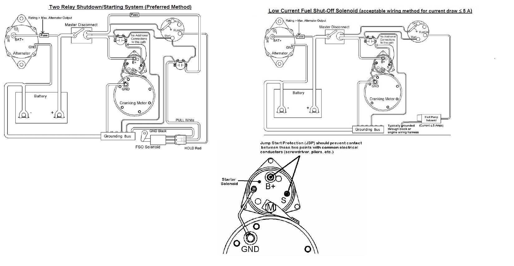
Basic Fuel Shutoff Solenoid And Starter Wiring Information Seaboard Marine
The image title is Basic Fuel Shutoff Solenoid And Starter Wiring Information Seaboard Marine, features dimensions of width 1648 px and height 852 px, with a file size of 1648 x 852 px. This image image/jpeg type visual are source from www.sbmar.com.
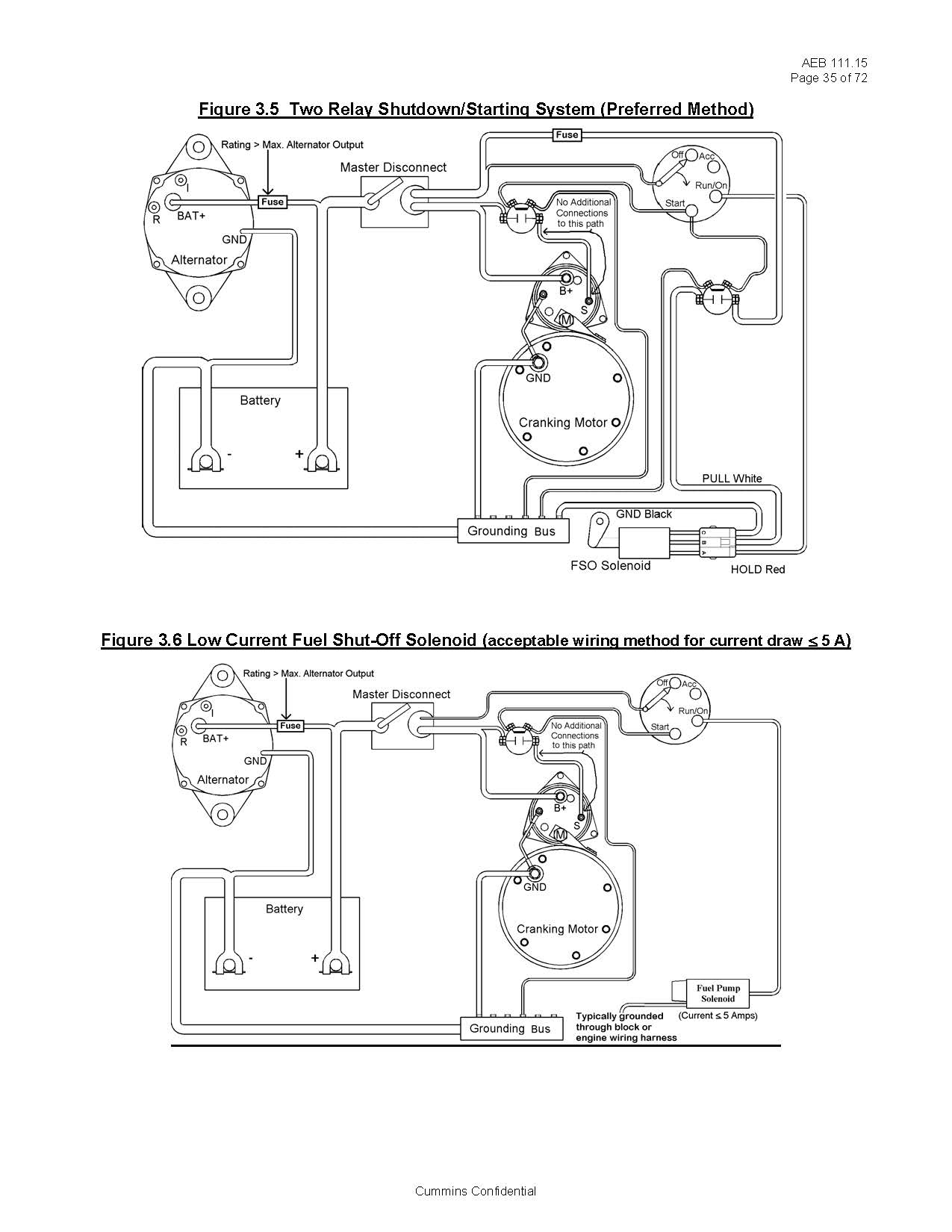
Basic Fuel Shutoff Solenoid And Starter Wiring Information Seaboard Marine
The image title is Basic Fuel Shutoff Solenoid And Starter Wiring Information Seaboard Marine, features dimensions of width 1275 px and height 1650 px, with a file size of 1275 x 1650. This image image/jpeg type visual are source from www.sbmar.com.
Starter Solenoid Wiring Diagram 3 Pole Starter Starter Motor Motorcycle Wiring Car Mechanic
The image title is Starter Solenoid Wiring Diagram 3 Pole Starter Starter Motor Motorcycle Wiring Car Mechanic, features dimensions of width 700 px and height 647 px, with a file size of 700 x 647. This image image/jpeg type visual are source from www.pinterest.jp.
Starter Solenoid Wiring Diagram 3 Pole Starter Diagram Easy Car Electrics YouTube
The image title is Starter Solenoid Wiring Diagram 3 Pole Starter Diagram Easy Car Electrics YouTube, features dimensions of width 1280 px and height 720 px, with a file size of 1280 x 720. This image image/jpeg type visual are source from m.youtube.com
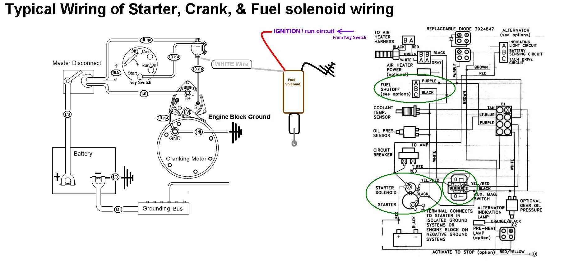
Fuel Shutoff Solenoid Wiring 101 Seaboard Marine
The image title is Fuel Shutoff Solenoid Wiring 101 Seaboard Marine, features dimensions of width 1830 px and height 902 px, with a file size of 1830 x 902. This image image/jpeg type visual are source from www.sbmar.com.
Fuel Shutoff Solenoid Wiring 101 Seaboard Marine
The image title is Fuel Shutoff Solenoid Wiring 101 Seaboard Marine, features dimensions of width 1372 px and height 686 px, with a file size of 1372 x 686. This image image/jpeg type visual are source from www.sbmar.com.
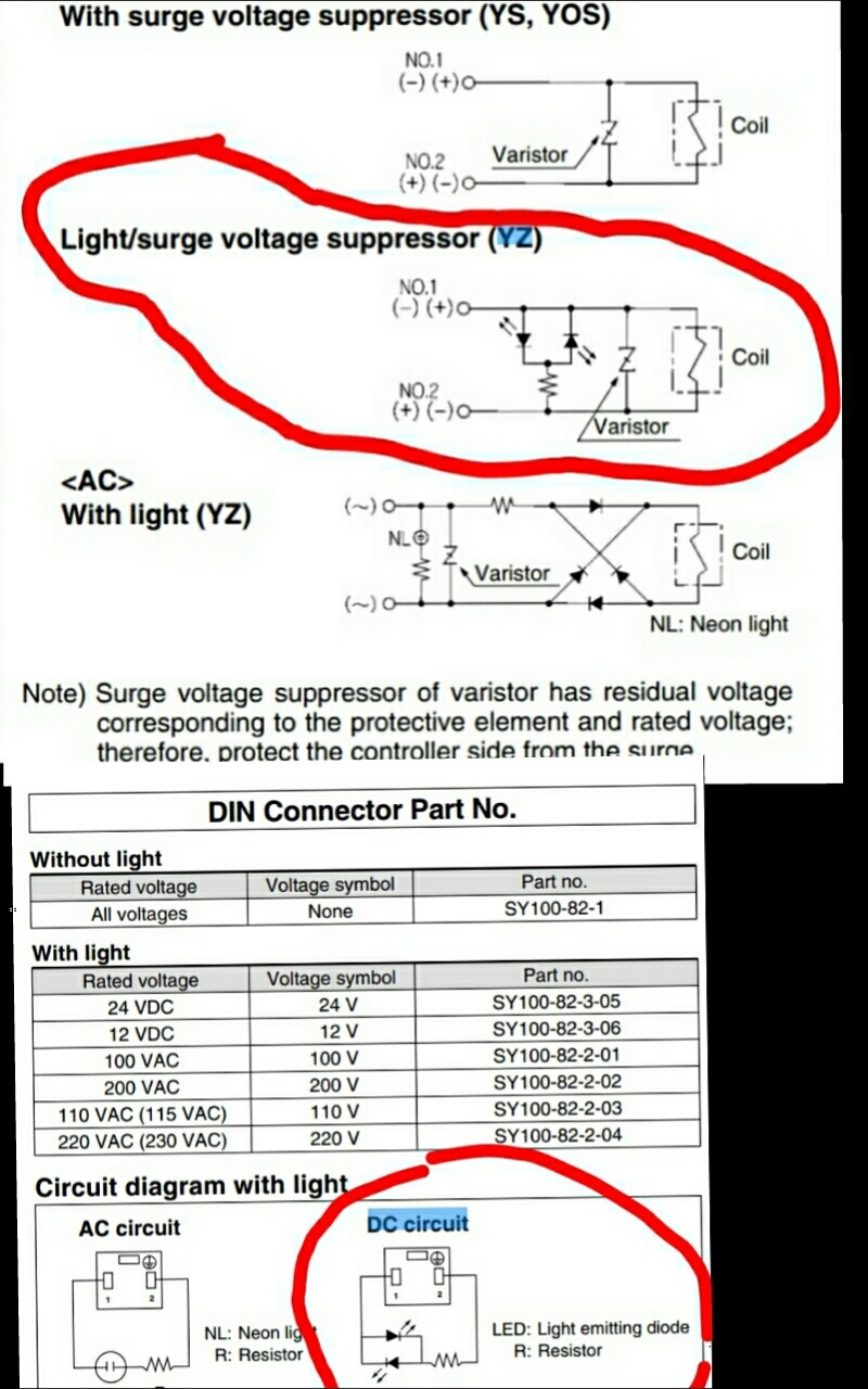
How To Wiring DC Solenoid Valve With 3 Wire General Electronics Arduino Forum
The image title is How To Wiring DC Solenoid Valve With 3 Wire General Electronics Arduino Forum, features dimensions of width 800 px and height 1280 px, with a file size of 800 x 1280.
The images on this page, sourced from Google for educational purposes, may be copyrighted. If you own an image and wish its removal or have copyright concerns, please contact us. We aim to promptly address these issues in compliance with our copyright policy and DMCA standards. Your cooperation is appreciated.
Related Keywords to 3 Wire Solenoid Wiring Diagram:
3 prong solenoid wiring diagram,3 wire fuel solenoid wiring diagram,3 wire hydraulic solenoid wiring diagram,3 wire solenoid valve wiring diagram,3 wire solenoid wiring diagram
