Table of Contents
The Value of 1756-If16 Wiring Diagram
When it comes to industrial automation and control systems, having accurate and detailed wiring diagrams is crucial for ensuring smooth operations and troubleshooting potential issues. One such essential component is the 1756-If16 Wiring Diagram, which provides a comprehensive layout of connections and configurations for the Allen-Bradley 1756-If16 module. This wiring diagram serves as a vital tool for engineers, technicians, and maintenance professionals in understanding the wiring requirements and functionality of the 1756-If16 module.
The Importance of 1756-If16 Wiring Diagram
The 1756-If16 module is commonly used in industrial settings to monitor analog inputs such as temperature, pressure, flow, and other variables. To ensure accurate and reliable data acquisition, it is essential to correctly wire the module according to the manufacturer’s specifications. The 1756-If16 Wiring Diagram plays a crucial role in guiding users through the wiring process, from connecting field devices to configuring input channels and setting parameters.
Key Components of the Wiring Diagram
The 1756-If16 Wiring Diagram typically includes detailed information on the following key components:
- Input terminals and connectors
- Power supply connections
- Signal conditioning circuits
- Configuration switches and settings
Benefits of Using the Wiring Diagram
By following the 1756-If16 Wiring Diagram, users can benefit from:
- Ensuring correct wiring connections
- Preventing errors and misconfigurations
- Facilitating troubleshooting and maintenance
- Maximizing the performance of the 1756-If16 module
Guidelines for Effective Wiring
To make the most of the 1756-If16 Wiring Diagram, consider the following guidelines:
- Double-check all connections before applying power
- Label wires and terminals for easy identification
- Follow safety protocols and regulations
- Consult with experts or manuals for complex configurations
Conclusion
In conclusion, the 1756-If16 Wiring Diagram is a valuable resource for anyone working with the Allen-Bradley 1756-If16 module. By understanding its importance, utilizing its guidance, and adhering to best practices, users can ensure the efficient operation and longevity of their industrial automation systems. Whether you are a seasoned professional or a novice in the field, the 1756-If16 Wiring Diagram is your go-to reference for successful wiring and configuration.
Related to 1756-If16 Wiring Diagram
- 1500 Watt Electric Space Heater Wiring Diagram
- 150cc Scooter Gy6 150cc Wiring Diagram
- 1756 Ib16 Wiring Diagram
- 1756 If16 Wiring Diagram
- 1756 Of8 Wiring Diagram
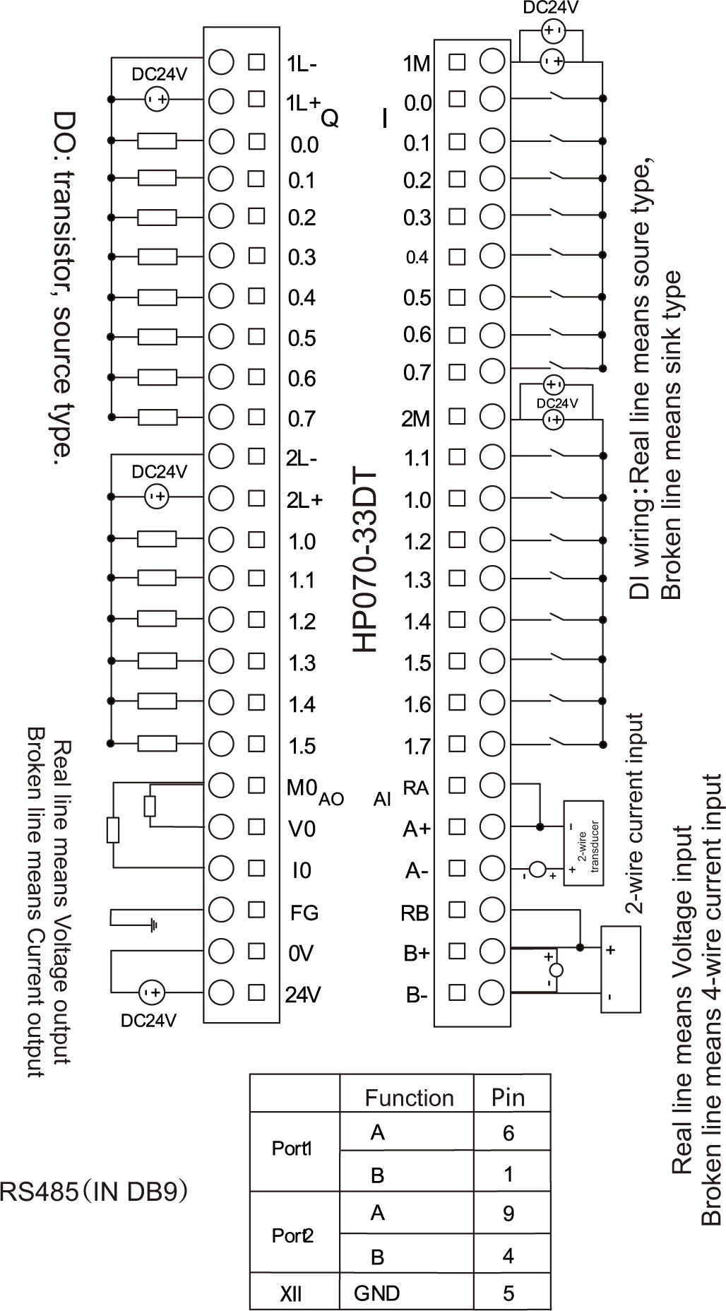
Index Of Images Hmi Wiring
The image title is Index Of Images Hmi Wiring, features dimensions of width 1028 px and height 1856 px, with a file size of 1028 x 1856 px. This image image/png type visual are source from www.anaheimautomation.com.
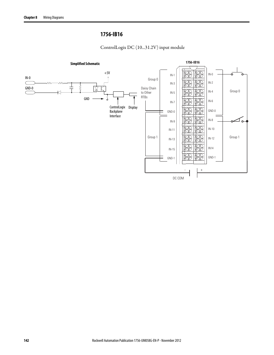
1756 Ib16 Controllogix Dc 10 V Input Module Rockwell Automation 1756 XXXX ControlLogix Digital I O Modules User Manual Page 142 258
The image title is 1756 Ib16 Controllogix Dc 10 V Input Module Rockwell Automation 1756 XXXX ControlLogix Digital I O Modules User Manual Page 142 258, features dimensions of width 954 px and height 1235 px, with a file size of 954 x 1235 px. This image image/png type visual are source from www.manualsdir.com.
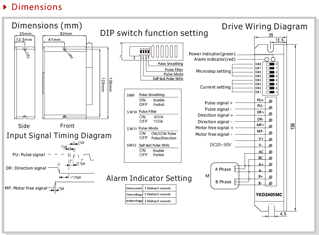
YKD2405MC
The image title is YKD2405MC, features dimensions of width 1064 px and height 786 px, with a file size of 1064 x 786. This image image/png type visual are source from www.yakotec.com.
Iv Conversion Module Wiring Diagram Continued Rockwell Automation 1492 CM800 LA002 Field Wire Conv Module For Modicon B877 111 To 1756 IF16 User Manual Page 3 4 Original Mode
The image title is Iv Conversion Module Wiring Diagram Continued Rockwell Automation 1492 CM800 LA002 Field Wire Conv Module For Modicon B877 111 To 1756 IF16 User Manual Page 3 4 Original Mode, features dimensions of width 954 px and height 1235 px, with a file size of 954 x 1235. This image image/png type visual are source from www.manualsdir.com.
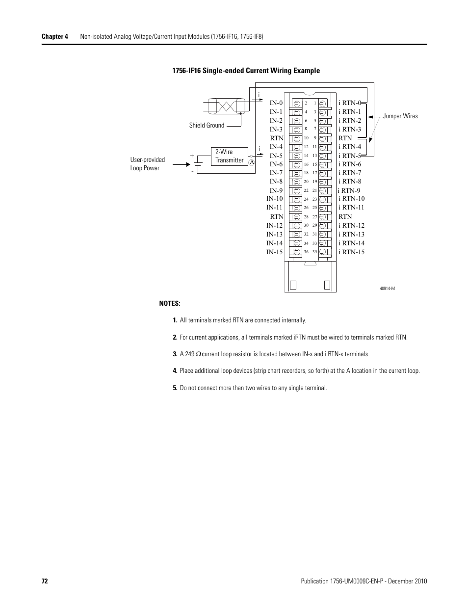
Rockwell Automation 1756 XXXX ControlLogix Analog I O Modules User Manual Page 72 401
The image title is Rockwell Automation 1756 XXXX ControlLogix Analog I O Modules User Manual Page 72 401, features dimensions of width 954 px and height 1235 px, with a file size of 954 x 1235. This image image/png type visual are source from www.manualsdir.com
Iv Conversion Module Wiring Diagram Continued Rockwell Automation 1492 CM800 LA001 Field Wire Conv Module For Modicon B875 111 To 1756 IF16 User Manual Page 3 4 Original Mode
The image title is Iv Conversion Module Wiring Diagram Continued Rockwell Automation 1492 CM800 LA001 Field Wire Conv Module For Modicon B875 111 To 1756 IF16 User Manual Page 3 4 Original Mode, features dimensions of width 954 px and height 1235 px, with a file size of 954 x 1235. This image image/png type visual are source from www.manualsdir.com.
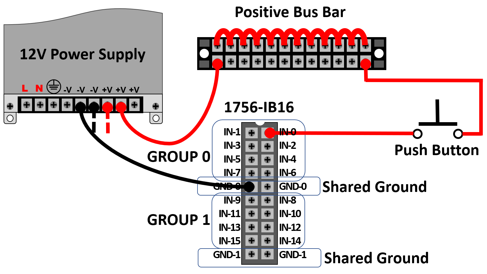
Learning RSLogix 5000 Programming Second Edition
The image title is Learning RSLogix 5000 Programming Second Edition, features dimensions of width 1625 px and height 915 px, with a file size of 1625 x 915. This image image/png type visual are source from subscription.packtpub.com.
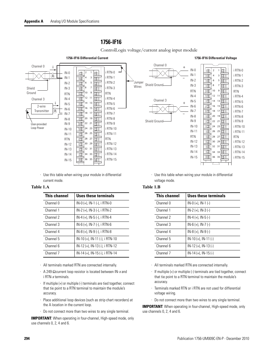
1756 If16 Controllogix Voltage Current Analog Input Module Rockwell Automation 1756 XXXX ControlLogix Analog I O Modules User Manual Page 294 401 Original Mode
The image title is 1756 If16 Controllogix Voltage Current Analog Input Module Rockwell Automation 1756 XXXX ControlLogix Analog I O Modules User Manual Page 294 401 Original Mode, features dimensions of width 954 px and height 1235 px, with a file size of 954 x 1235.
The images on this page, sourced from Google for educational purposes, may be copyrighted. If you own an image and wish its removal or have copyright concerns, please contact us. We aim to promptly address these issues in compliance with our copyright policy and DMCA standards. Your cooperation is appreciated.
Related Keywords to 1756-If16 Wiring Diagram:
1756 if16 wiring diagram,1756-ib16 wiring diagram,1756-if16h wiring diagram,ab 1756-if16 wiring diagram,rockwell 1756 if16 wiring diagram
