Table of Contents
The Value of 1756 If16 Wiring Diagram
The 1756 If16 Wiring Diagram is a crucial tool for anyone working with industrial automation systems. Whether you are a seasoned professional or just starting in the field, understanding the intricacies of this wiring diagram can make a significant difference in your efficiency and effectiveness. By delving into the details of the 1756 If16 Wiring Diagram, you unlock a wealth of insights that can streamline your processes, troubleshoot issues more effectively, and optimize the performance of your automation system.
Understanding the Basics
Before we dive deeper into the specifics of the 1756 If16 Wiring Diagram, let’s establish a foundational understanding of its importance. This wiring diagram serves as a blueprint for connecting various components within an industrial automation system, providing a clear visual representation of how signals flow and interact. By following this diagram accurately, you ensure that all components work harmoniously together, minimizing the risk of errors or malfunctions.
Key Components
Within the 1756 If16 Wiring Diagram, you will encounter a range of key components that play essential roles in the overall functionality of the system. These components may include input modules, output modules, power supplies, communication modules, and more. Each component is interconnected in a specific way to facilitate the smooth operation of the automation system.
Benefits of Using the 1756 If16 Wiring Diagram
Now that we have established the foundational importance of the 1756 If16 Wiring Diagram, let’s explore the tangible benefits it offers to professionals in the field of industrial automation. By utilizing this wiring diagram effectively, you can:
- Ensure accurate connections between components
- Facilitate troubleshooting processes
- Optimize system performance
- Enhance overall efficiency
Streamlining Operations
One of the primary advantages of the 1756 If16 Wiring Diagram is its ability to streamline operations within an industrial automation setting. By providing a clear visual guide for connecting components, this diagram eliminates guesswork and reduces the likelihood of errors during installation or maintenance tasks. This streamlined approach can save time and resources while improving the overall reliability of the system.
Best Practices for Using the 1756 If16 Wiring Diagram
To make the most of the 1756 If16 Wiring Diagram, it is essential to follow some best practices that enhance its effectiveness. Consider the following tips:
- Refer to the diagram regularly when working on the automation system
- Double-check connections before powering up the system
- Document any modifications or changes made to the wiring
- Keep a digital or physical copy of the diagram for easy access
Continuous Learning and Improvement
In the ever-evolving field of industrial automation, staying updated on the latest technologies and practices is crucial for success. By regularly reviewing and understanding the 1756 If16 Wiring Diagram, you can enhance your knowledge and skills, ultimately improving your performance in the field. Embrace a mindset of continuous learning and improvement to excel in your role and contribute effectively to your organization’s success.
Related to 1756 If16 Wiring Diagram
- 12v Wiring Power Wheels Wiring Diagram
- 14 3 Wiring Diagrams
- 1500 Watt Electric Space Heater Wiring Diagram
- 150cc Scooter Gy6 150cc Wiring Diagram
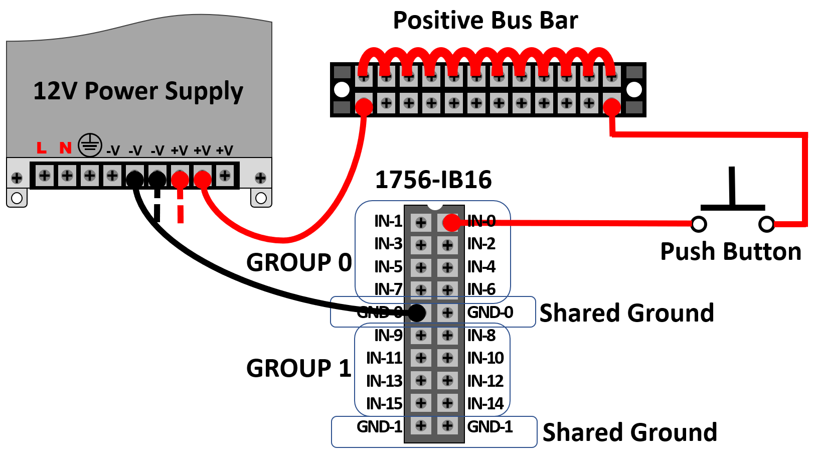
- 1756 Ib16 Wiring Diagram
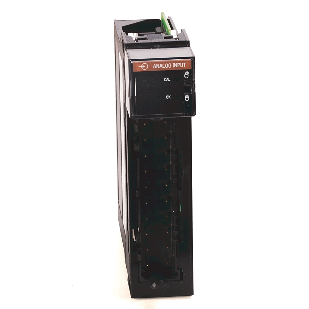
1756 IF6I Allen Bradley
The image title is 1756 IF6I Allen Bradley, features dimensions of width 1000 px and height 1000 px, with a file size of 1000 x 1000 px. This image image/jpeg type visual are source from www.rockwellautomation.com.
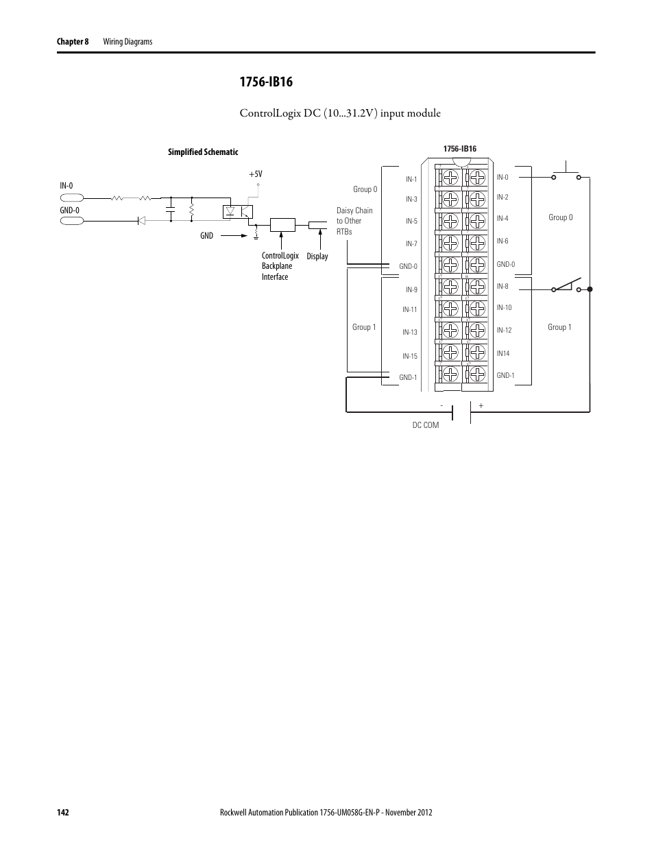
1756 Ib16 Controllogix Dc 10 V Input Module Rockwell Automation 1756 XXXX ControlLogix Digital I O Modules User Manual Page 142 258
The image title is 1756 Ib16 Controllogix Dc 10 V Input Module Rockwell Automation 1756 XXXX ControlLogix Digital I O Modules User Manual Page 142 258, features dimensions of width 954 px and height 1235 px, with a file size of 954 x 1235 px. This image image/png type visual are source from www.manualsdir.com.
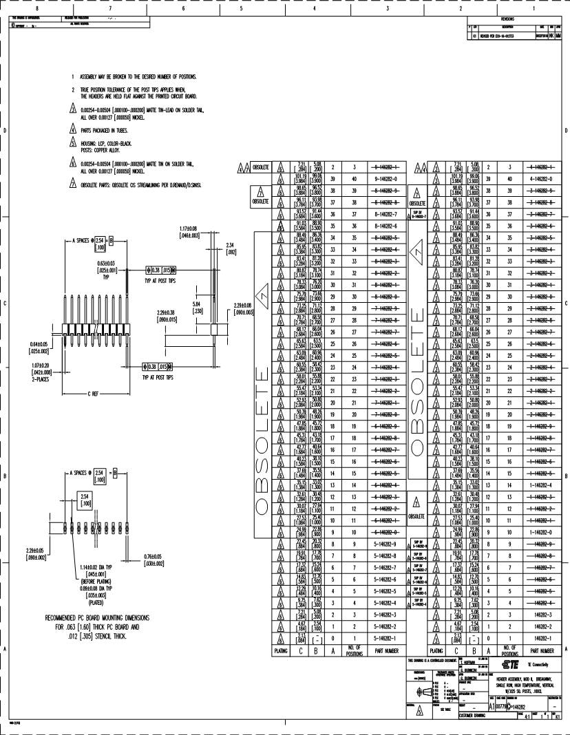
Tin 2 Position 1 Row 2 54 Mm Headers Breakaway Headers Wire Housings Datasheets Mouser
The image title is Tin 2 Position 1 Row 2 54 Mm Headers Breakaway Headers Wire Housings Datasheets Mouser, features dimensions of width 828 px and height 1068 px, with a file size of 828 x 1068. This image image/jpeg type visual are source from www.mouser.com.
Iv Conversion Module Wiring Diagram Continued Rockwell Automation 1492 CM800 LA002 Field Wire Conv Module For Modicon B877 111 To 1756 IF16 User Manual Page 3 4 Original Mode
The image title is Iv Conversion Module Wiring Diagram Continued Rockwell Automation 1492 CM800 LA002 Field Wire Conv Module For Modicon B877 111 To 1756 IF16 User Manual Page 3 4 Original Mode, features dimensions of width 954 px and height 1235 px, with a file size of 954 x 1235. This image image/png type visual are source from www.manualsdir.com.
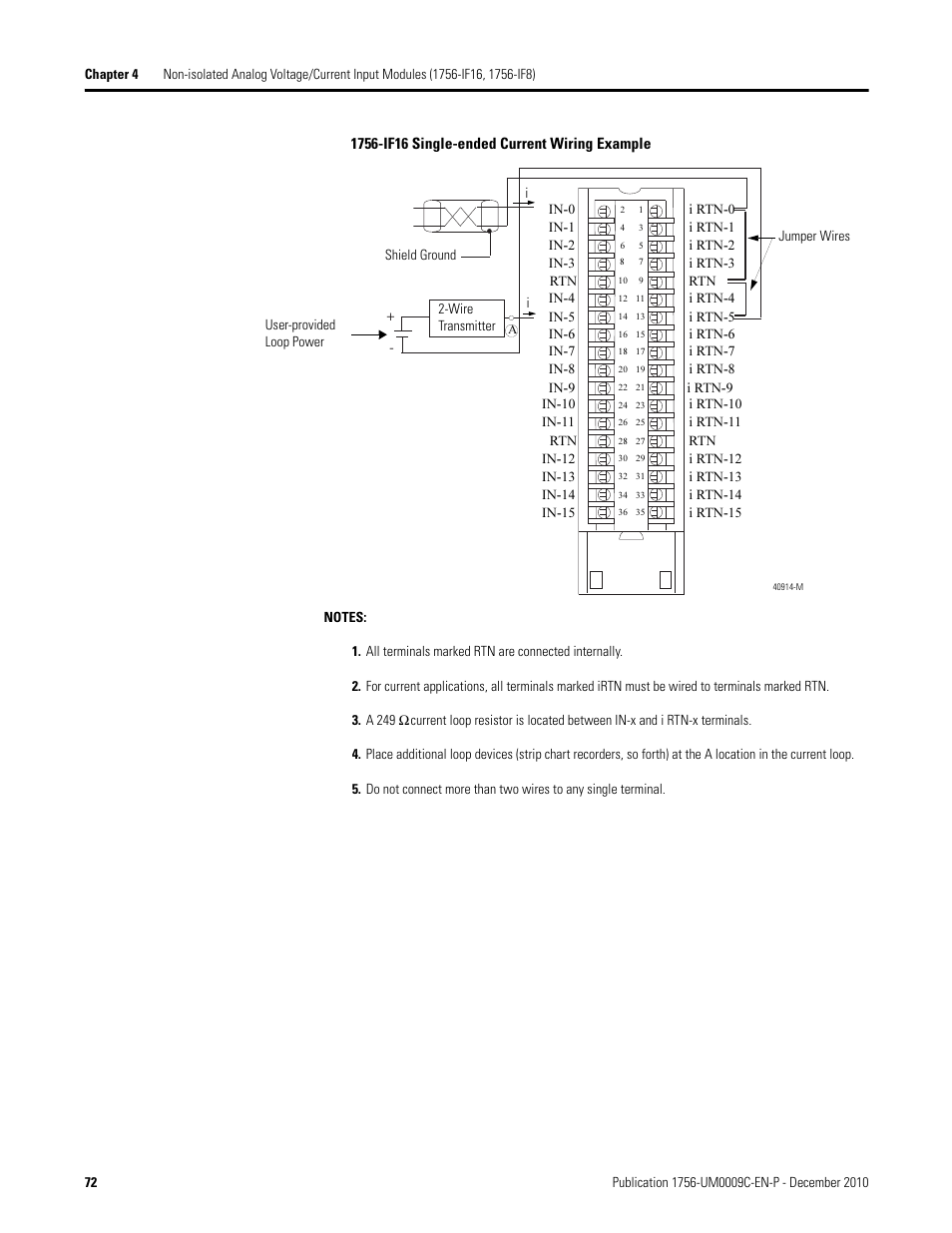
Rockwell Automation 1756 XXXX ControlLogix Analog I O Modules User Manual Page 72 401
The image title is Rockwell Automation 1756 XXXX ControlLogix Analog I O Modules User Manual Page 72 401, features dimensions of width 954 px and height 1235 px, with a file size of 954 x 1235. This image image/png type visual are source from www.manualsdir.com
Iv Conversion Module Wiring Diagram Continued Rockwell Automation 1492 CM800 LA001 Field Wire Conv Module For Modicon B875 111 To 1756 IF16 User Manual Page 3 4 Original Mode
The image title is Iv Conversion Module Wiring Diagram Continued Rockwell Automation 1492 CM800 LA001 Field Wire Conv Module For Modicon B875 111 To 1756 IF16 User Manual Page 3 4 Original Mode, features dimensions of width 954 px and height 1235 px, with a file size of 954 x 1235. This image image/png type visual are source from www.manualsdir.com.
Learning RSLogix 5000 Programming Second Edition
The image title is Learning RSLogix 5000 Programming Second Edition, features dimensions of width 1625 px and height 915 px, with a file size of 1625 x 915. This image image/png type visual are source from subscription.packtpub.com.
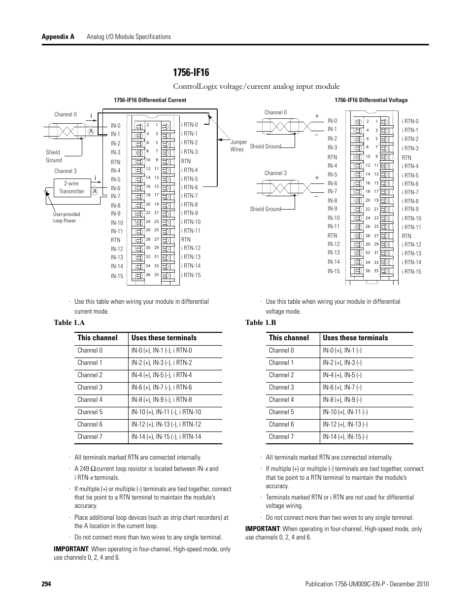
1756 If16 Controllogix Voltage Current Analog Input Module Rockwell Automation 1756 XXXX ControlLogix Analog I O Modules User Manual Page 294 401 Original Mode
The image title is 1756 If16 Controllogix Voltage Current Analog Input Module Rockwell Automation 1756 XXXX ControlLogix Analog I O Modules User Manual Page 294 401 Original Mode, features dimensions of width 954 px and height 1235 px, with a file size of 954 x 1235.
The images on this page, sourced from Google for educational purposes, may be copyrighted. If you own an image and wish its removal or have copyright concerns, please contact us. We aim to promptly address these issues in compliance with our copyright policy and DMCA standards. Your cooperation is appreciated.
Related Keywords to 1756 If16 Wiring Diagram:
1756 if16 wiring diagram,1756 if16 wiring diagram pdf,1756-ib16 wiring diagram,1756-if16h wiring diagram,ab 1756-if16 wiring diagram
