Table of Contents
Unlocking the Potential: Wiring Diagram For Potentiometer
In the world of electronics and circuitry, the potentiometer stands out as a versatile component that allows for precise control and adjustment of electrical signals. Whether you are a seasoned electronics enthusiast or a beginner looking to delve into the realm of circuit design, understanding how to wire a potentiometer is crucial for achieving desired outcomes in your projects. Let’s explore the ins and outs of wiring diagrams for potentiometers and how they can elevate your electronic creations to new heights.
The Basics of Potentiometers
Before diving into the wiring aspect, it’s essential to grasp the fundamental principles behind potentiometers. Also known as pots or variable resistors, potentiometers offer varying resistance levels that can be adjusted by rotating a knob or slider. This ability to control the flow of current makes potentiometers invaluable in applications where precision and flexibility are paramount.
Types of Potentiometers
Potentiometers come in different types, including linear and logarithmic variants. Linear potentiometers provide a consistent change in resistance as the knob is turned, making them ideal for applications requiring linear adjustments. On the other hand, logarithmic potentiometers offer a non-linear response, which is commonly used in audio equipment to mimic the human ear’s sensitivity to sound.
Components of a Potentiometer
A typical potentiometer consists of three terminals – the input terminal, output terminal, and wiper terminal. The input and output terminals are connected to the circuit, while the wiper terminal forms the adjustable connection point that determines the resistance value. Understanding the role of each terminal is crucial for correctly wiring a potentiometer.
Wiring Diagram For Potentiometer
Now that we’ve covered the basics, let’s delve into the wiring diagram for a potentiometer. Whether you’re incorporating a potentiometer into a volume control circuit, dimmer switch, or sensor calibration setup, the wiring configuration remains consistent across various applications.
Step-by-Step Wiring Guide
- Identify the terminals of the potentiometer – input, output, and wiper.
- Connect the input terminal to the power source or ground, depending on the circuit requirements.
- Link the output terminal to the load or component that will be controlled by the potentiometer.
- Wire the wiper terminal to the point in the circuit where you want to adjust the resistance.
- Ensure proper insulation and secure connections to prevent short circuits or signal interference.
Benefits of Using Potentiometers
Incorporating potentiometers into your electronic projects offers a myriad of benefits, from precise control over parameters like volume and brightness to fine-tuning sensor readings for enhanced accuracy. By mastering the art of wiring potentiometers, you unlock a world of possibilities for customizing and optimizing your circuits to meet specific requirements.
Conclusion
The wiring diagram for potentiometers serves as a roadmap to harnessing their full potential in electronic applications. By understanding the underlying principles and following the proper wiring guidelines, you can leverage potentiometers to achieve tailored solutions that elevate your projects to the next level. Whether you’re embarking on a new electronics venture or seeking to enhance existing designs, the versatility of potentiometers makes them a valuable tool in your arsenal of components.
Related to Wiring Diagram For Potentiometer
- Wiring Diagram For Photocell
- Wiring Diagram For Pioneer Radio
- Wiring Diagram For Plug
- Wiring Diagram For Pool Pump
- Wiring Diagram For Pool Pump Timer
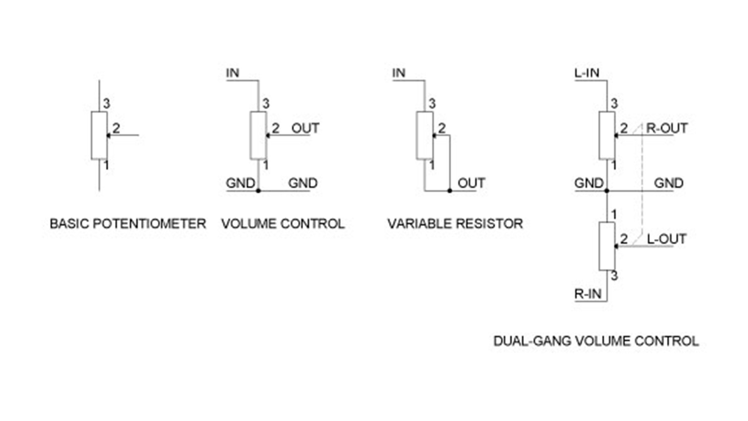
D7P POT Potentiomater Wiring Sprecher Schuh
The image title is D7P POT Potentiomater Wiring Sprecher Schuh, features dimensions of width 2400 px and height 1350 px, with a file size of 2400 x 1350 px. This image image/jpeg type visual are source from www.sprecherschuh.com.
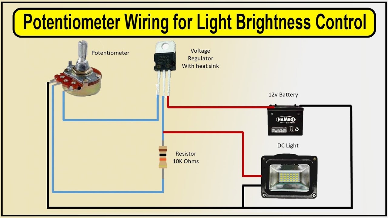
Potentiometer Wiring For Light Brightness Control LED Potentiometer YouTube
The image title is Potentiometer Wiring For Light Brightness Control LED Potentiometer YouTube, features dimensions of width 1280 px and height 720 px, with a file size of 1280 x 720 px. This image image/jpeg type visual are source from www.youtube.com.
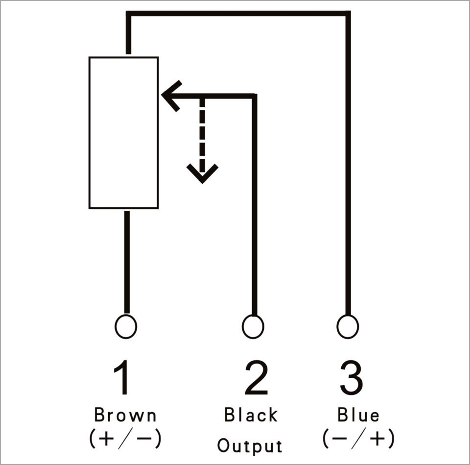
Potentiometer Wiring A Comprehensive Guide
The image title is Potentiometer Wiring A Comprehensive Guide, features dimensions of width 960 px and height 949 px, with a file size of 960 x 949. This image image/jpeg type visual are source from www.nextpcb.com.
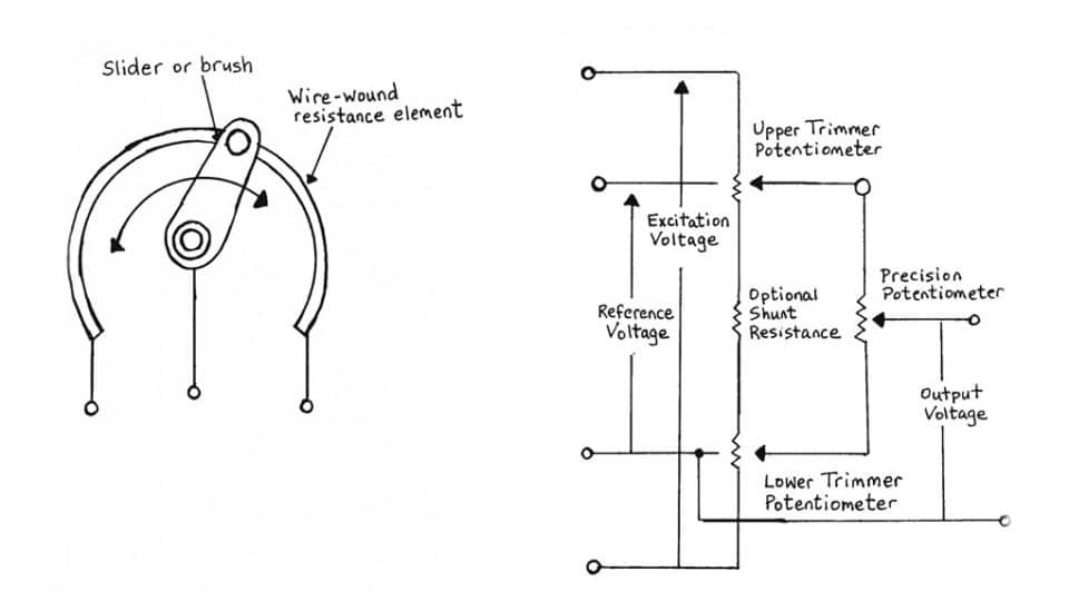
Potentiometers Basic Principles
The image title is Potentiometers Basic Principles, features dimensions of width 960 px and height 540 px, with a file size of 960 x 540. This image image/jpeg type visual are source from epci.eu.
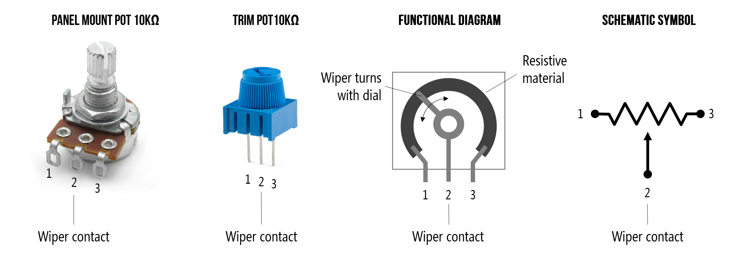
L4 Potentiometers Physical Computing
The image title is L4 Potentiometers Physical Computing, features dimensions of width 2337 px and height 827 px, with a file size of 2337 x 827. This image image/png type visual are source from makeabilitylab.github.io
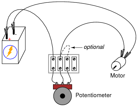
Power Supply Wiring A Potentiometer For A Positive Voltage Electrical Engineering Stack Exchange
The image title is Power Supply Wiring A Potentiometer For A Positive Voltage Electrical Engineering Stack Exchange, features dimensions of width 445 px and height 348 px, with a file size of 445 x 348. This image image/png type visual are source from electronics.stackexchange.com.
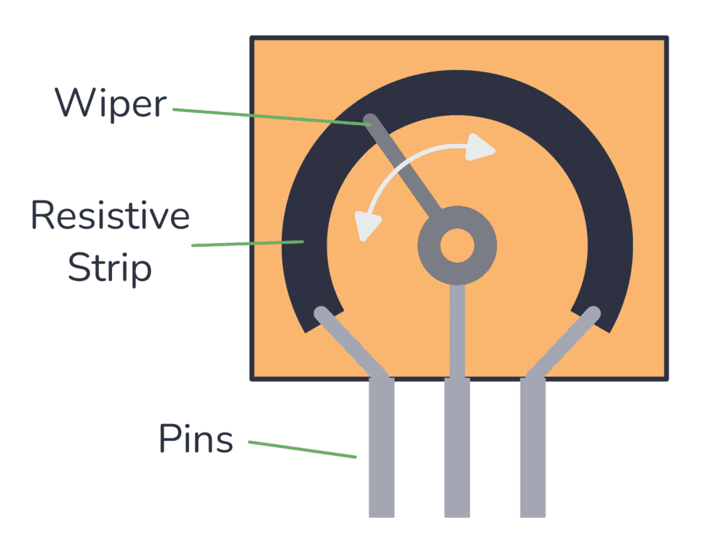
The Potentiometer Pinout Wiring And How It Works
The image title is The Potentiometer Pinout Wiring And How It Works, features dimensions of width 1024 px and height 793 px, with a file size of 1024 x 793. This image image/png type visual are source from www.build-electronic-circuits.com.
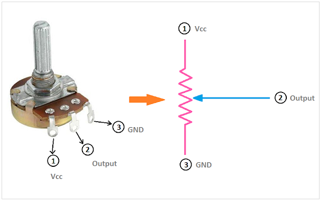
Potentiometer Circuit Circuit Diagram Electronics Basics Electronic Circuit Projects
The image title is Potentiometer Circuit Circuit Diagram Electronics Basics Electronic Circuit Projects, features dimensions of width 640 px and height 404 px, with a file size of 640 x 404.
The images on this page, sourced from Google for educational purposes, may be copyrighted. If you own an image and wish its removal or have copyright concerns, please contact us. We aim to promptly address these issues in compliance with our copyright policy and DMCA standards. Your cooperation is appreciated.
Related Keywords to Wiring Diagram For Potentiometer:
circuit diagram for potentiometer,circuit diagram potentiometer symbol,does it matter which way you wire a potentiometer,how to wire a potentiometer,wiring diagram for potentiometer
