Table of Contents
Exploring the Value of Wiring Diagram For O2 Sensor
The Importance of Wiring Diagram For O2 Sensor
When it comes to automotive diagnostics and repairs, having access to a thorough wiring diagram for the O2 sensor can be invaluable. The O2 sensor, also known as the oxygen sensor, plays a crucial role in monitoring and regulating the air-fuel ratio in your vehicle’s engine. Understanding how this sensor works and being able to interpret its wiring diagram can help you identify issues, troubleshoot problems, and ultimately keep your vehicle running smoothly. Let’s delve into the world of O2 sensor wiring diagrams and explore their significance in automotive maintenance.
Understanding the Basics of O2 Sensor Wiring Diagram
Before we dive into the intricacies of O2 sensor wiring diagrams, let’s first establish a basic understanding of how these sensors function. O2 sensors are responsible for measuring the amount of oxygen in the exhaust gases exiting the engine. Based on this data, the engine control unit (ECU) adjusts the air-fuel mixture to optimize combustion efficiency. The wiring diagram for the O2 sensor outlines the electrical connections and components involved in this process, providing a roadmap for diagnosing and resolving issues.
Benefits of Having a Comprehensive Wiring Diagram
Having a detailed wiring diagram for the O2 sensor offers several advantages for both DIY enthusiasts and professional mechanics. Here are some key benefits of leveraging this resource:
Accurate Diagnosis: A wiring diagram helps you pinpoint the exact location of sensor wires, connectors, and power sources, facilitating precise diagnosis of faults.
Efficient Troubleshooting: By following the diagram, you can systematically test each component and identify the root cause of O2 sensor malfunctions.
Effective Repairs: With a clear understanding of the wiring layout, you can swiftly make repairs or replacements as needed, minimizing downtime.
Interpreting and Using Wiring Diagrams Effectively
To make the most of a wiring diagram for the O2 sensor, it’s essential to know how to interpret the information provided. Here are some tips for effectively using these diagrams:
Familiarize Yourself with Symbols: Wiring diagrams use specific symbols to represent different components and connections. Take the time to understand these symbols to decipher the diagram accurately.
Follow the Wiring Path: Trace the wiring path from the sensor to the ECU, noting any junctions, splices, or grounds along the way. This will help you identify potential points of failure.
Check for Continuity: Use a multimeter to test for continuity in the sensor circuit, ensuring that all connections are intact and functioning properly.
Conclusion
In conclusion, a wiring diagram for the O2 sensor serves as a valuable resource for diagnosing, troubleshooting, and repairing issues related to this critical component in your vehicle’s engine. By understanding the fundamentals of O2 sensor wiring diagrams and applying them effectively, you can streamline your maintenance processes and ensure optimal performance of your vehicle. Whether you’re a seasoned mechanic or a DIY enthusiast, having access to comprehensive wiring diagrams can make a significant difference in your automotive endeavors.
Related to Wiring Diagram For O2 Sensor
- Wiring Diagram For Msd Ignition
- Wiring Diagram For Nest
- Wiring Diagram For Nest Thermostat
- Wiring Diagram For Nest Thermostat E
- Wiring Diagram For Neutral Safety Switch
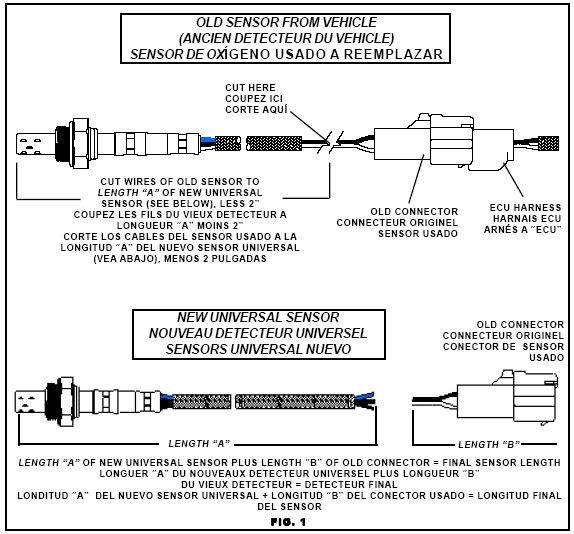
Sensor Schematics At DuckDuckGo Electronic Schematics Sensor Diagram
The image title is Sensor Schematics At DuckDuckGo Electronic Schematics Sensor Diagram, features dimensions of width 574 px and height 534 px, with a file size of 574 x 534 px. This image image/jpeg type visual are source from www.pinterest.com.
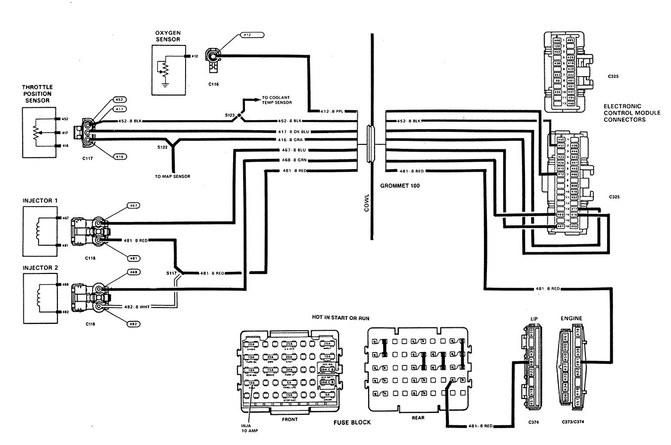
GM 4 Wire O2 Sensor Wiring Diagram Chevy 1989 Oxygen Sensor Wiring
The image title is GM 4 Wire O2 Sensor Wiring Diagram Chevy 1989 Oxygen Sensor Wiring, features dimensions of width 1356 px and height 900 px, with a file size of 1356 x 900 px. This image image/png type visual are source from www.justanswer.com.
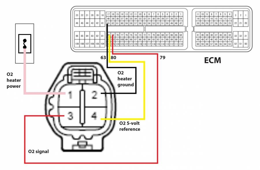
Does An Upstream O2 Sensor Have A Fuse 01 T C 3 8 Moparts Forums
The image title is Does An Upstream O2 Sensor Have A Fuse 01 T C 3 8 Moparts Forums, features dimensions of width 900 px and height 589 px, with a file size of 900 x 589. This image image/jpeg type visual are source from board.moparts.org.
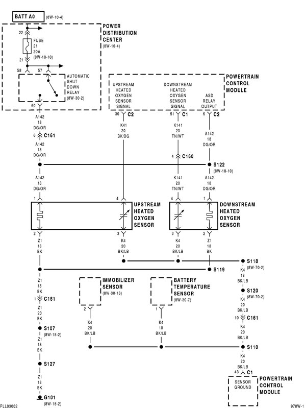
O2 Sensor Wiring Diagram Neons
The image title is O2 Sensor Wiring Diagram Neons, features dimensions of width 600 px and height 799 px, with a file size of 600 x 799. This image image/jpeg type visual are source from forums.neons.org.
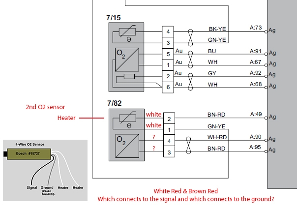
Wiring Diagram Help O2 Sensor SwedeSpeed Volvo Performance Forum
The image title is Wiring Diagram Help O2 Sensor SwedeSpeed Volvo Performance Forum, features dimensions of width 604 px and height 433 px, with a file size of 604 x 433. This image image/jpeg type visual are source from www.swedespeed.com
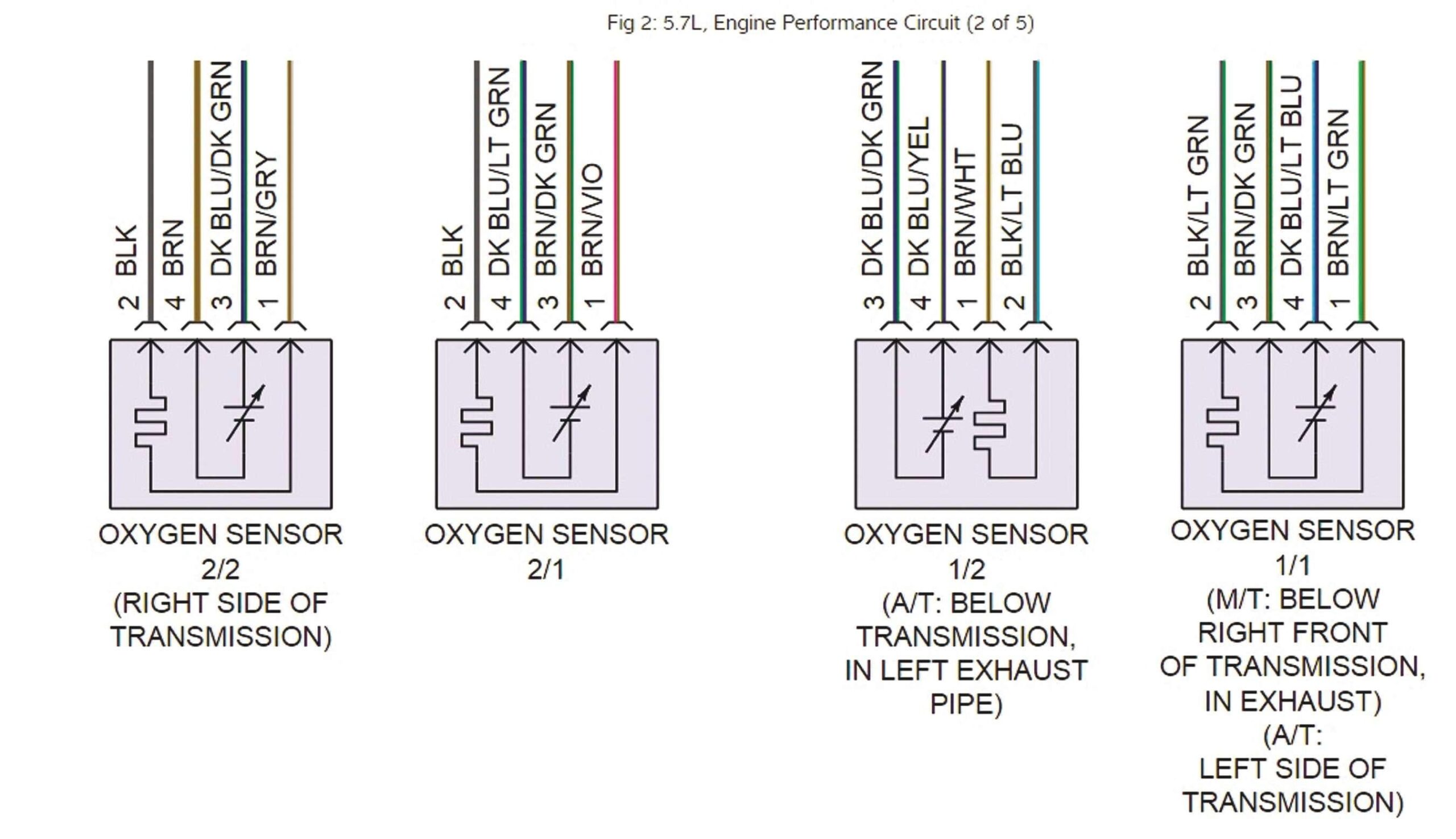
Tracing Sensor Wiring And Checking For Lazy Sensors Issuu
The image title is Tracing Sensor Wiring And Checking For Lazy Sensors Issuu, features dimensions of width 2560 px and height 1475 px, with a file size of 2702 x 1557. This image image/jpeg type visual are source from issuu.com.
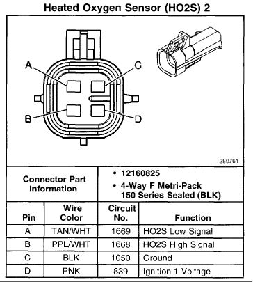
Toyota Oxygen Sensor Pinout Electrical Wiring Diagram Map Sensor Sensor
The image title is Toyota Oxygen Sensor Pinout Electrical Wiring Diagram Map Sensor Sensor, features dimensions of width 364 px and height 405 px, with a file size of 364 x 405. This image image/jpeg type visual are source from www.pinterest.com.
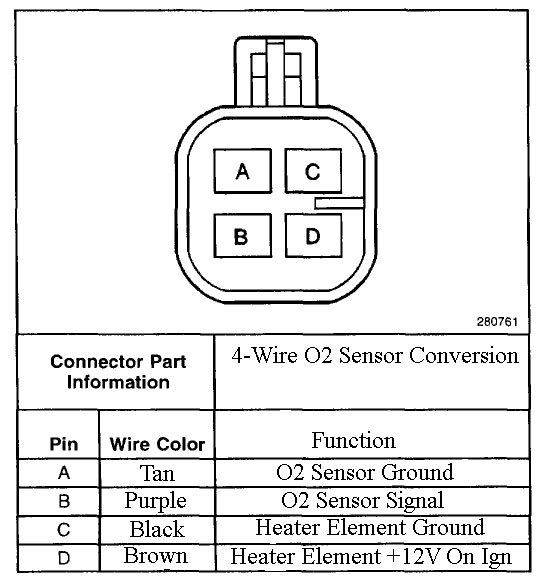
4 Wire O2 Sensor Wiring Diagram Toyota Sensor Toyota Oxygen
The image title is 4 Wire O2 Sensor Wiring Diagram Toyota Sensor Toyota Oxygen, features dimensions of width 560 px and height 585 px, with a file size of 560 x 585.
The images on this page, sourced from Google for educational purposes, may be copyrighted. If you own an image and wish its removal or have copyright concerns, please contact us. We aim to promptly address these issues in compliance with our copyright policy and DMCA standards. Your cooperation is appreciated.
Related Keywords to Wiring Diagram For O2 Sensor:
wiring diagram 02 sensor,wiring diagram for 4 wire o2 sensor,wiring diagram for bosch o2 sensor,wiring diagram for o2 sensor,wiring diagram for oxygen sensor
