Table of Contents
Exploring the Value of Wiring Diagram For Heat Pump
Exploring the Value of Wiring Diagram For Heat Pump
When it comes to understanding the intricate workings of a heat pump system, having a comprehensive wiring diagram can be a game-changer. A wiring diagram serves as a roadmap that guides technicians and DIY enthusiasts alike through the complexities of electrical connections within a heat pump. By providing a visual representation of how components are linked together, a wiring diagram not only simplifies troubleshooting and repairs but also enhances overall system efficiency. Let’s delve into the world of wiring diagrams for heat pumps and uncover the valuable insights they offer.
The Basics of Wiring Diagrams for Heat Pumps
At the core of any heat pump system lies its electrical wiring, which connects various components such as the compressor, condenser, evaporator, and thermostat. A wiring diagram illustrates how these components are interconnected and powered, enabling technicians to pinpoint potential issues and ensure proper functioning. By decoding the symbols and color codes used in the diagram, individuals can navigate through the intricate network of wires with ease.
Key Components in a Wiring Diagram
A typical wiring diagram for a heat pump includes key components such as:
Compressor
Condenser
Evaporator
Thermostat
Reversing valve
Benefits of Using a Wiring Diagram
The advantages of consulting a wiring diagram for a heat pump system are manifold:
Enhanced Troubleshooting: By following the wiring diagram, technicians can quickly identify and address electrical issues, minimizing downtime.
Efficient Repairs: With a clear visual guide, repairs become more efficient and accurate, leading to cost savings for homeowners and businesses alike.
Optimized Performance: Understanding the wiring layout enables users to optimize system performance and ensure energy efficiency.
Interpreting Color Codes in Wiring Diagrams
Color coding plays a crucial role in wiring diagrams, with each color representing a specific function or connection. Common color codes used in heat pump wiring diagrams include:
Red: Power supply
Blue: Cooling mode
Yellow: Heating mode
Green: Fan control
By understanding these color codes, users can easily trace and troubleshoot electrical pathways within the heat pump system.
Conclusion
In conclusion, a wiring diagram for a heat pump is an invaluable tool that simplifies the complexities of electrical connections and enhances system efficiency. By decoding symbols, color codes, and component layouts, individuals can navigate through the intricacies of a heat pump system with confidence and precision. Whether you are a seasoned technician or a DIY enthusiast, harnessing the power of a wiring diagram can elevate your understanding and streamline your maintenance efforts.
Related to Wiring Diagram For Heat Pump
- Wiring Diagram For Goodman Heat Pump
- Wiring Diagram For Gooseneck Trailer
- Wiring Diagram For Gy6 150cc
- Wiring Diagram For Hampton Bay Ceiling Fan
- Wiring Diagram For Harbor Breeze Ceiling Fan
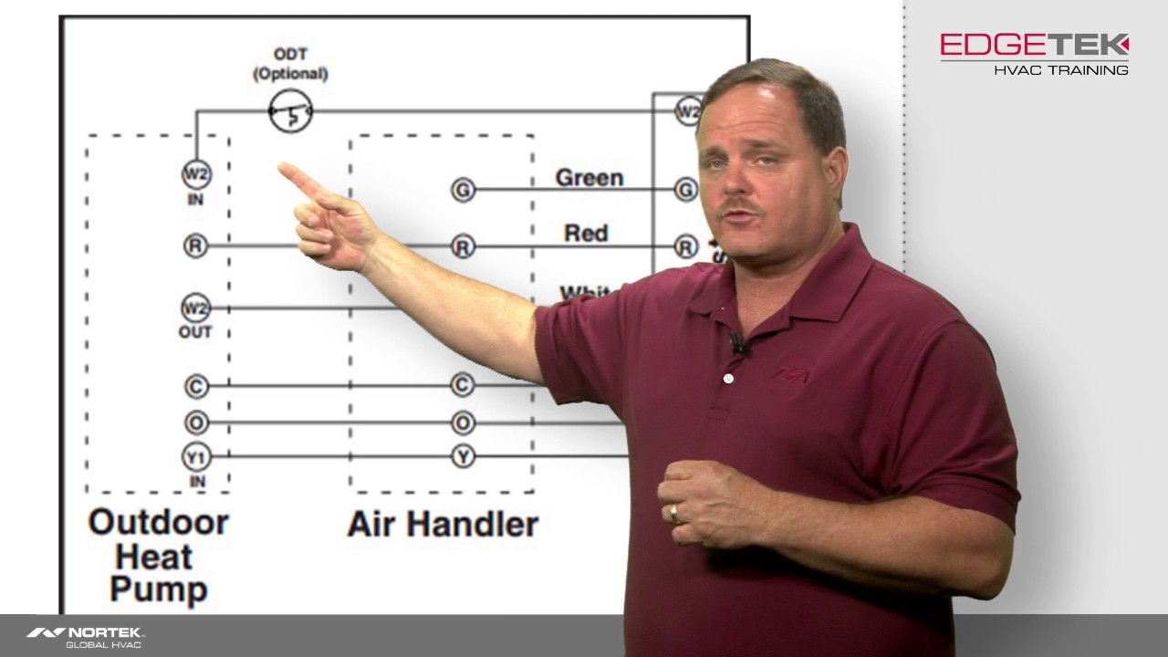
Wiring Of A Single Stage Heat Pump YouTube
The image title is Wiring Of A Single Stage Heat Pump YouTube, features dimensions of width 1280 px and height 720 px, with a file size of 1280 x 720 px. This image image/jpeg type visual are source from m.youtube.com.
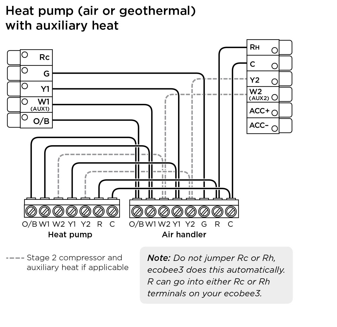
Hvac Ecobee3 Wiring With Heat Pump Home Improvement Stack Exchange
The image title is Hvac Ecobee3 Wiring With Heat Pump Home Improvement Stack Exchange, features dimensions of width 1143 px and height 1108 px, with a file size of 1143 x 1108 px. This image image/jpeg type visual are source from diy.stackexchange.com.
42 Goodman Heat Pump Thermostat Wiring Diagram
The image title is 42 Goodman Heat Pump Thermostat Wiring Diagram, features dimensions of width 1023 px and height 569 px, with a file size of 1023 x 569. This image image/jpeg type visual are source from www.pinterest.com.
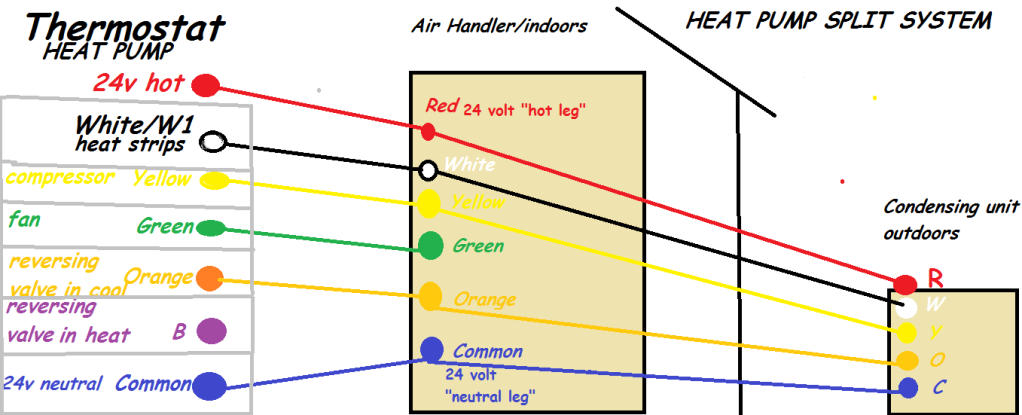
Hvac Why Does My Heat Pump Wiring Diagram Show 7 Wires Going To The Thermostat But The Thermostat Only Says It Needs 5 Home Improvement Stack Exchange
The image title is Hvac Why Does My Heat Pump Wiring Diagram Show 7 Wires Going To The Thermostat But The Thermostat Only Says It Needs 5 Home Improvement Stack Exchange, features dimensions of width 1022 px and height 415 px, with a file size of 1022 x 415. This image image/png type visual are source from diy.stackexchange.com.
Carrier Heat Pump Wiring Diagram Carrier Heat Pump Thermostat Wiring Heat Pump
The image title is Carrier Heat Pump Wiring Diagram Carrier Heat Pump Thermostat Wiring Heat Pump, features dimensions of width 735 px and height 568 px, with a file size of 735 x 568. This image image/jpeg type visual are source from www.pinterest.com
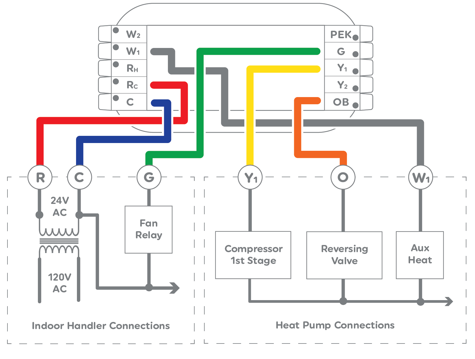
Cync Thermostat Wiring Configuration And Installation Guide
The image title is Cync Thermostat Wiring Configuration And Installation Guide, features dimensions of width 1655 px and height 1250 px, with a file size of 1655 x 1250. This image image/png type visual are source from cyncsupport.gelighting.com.
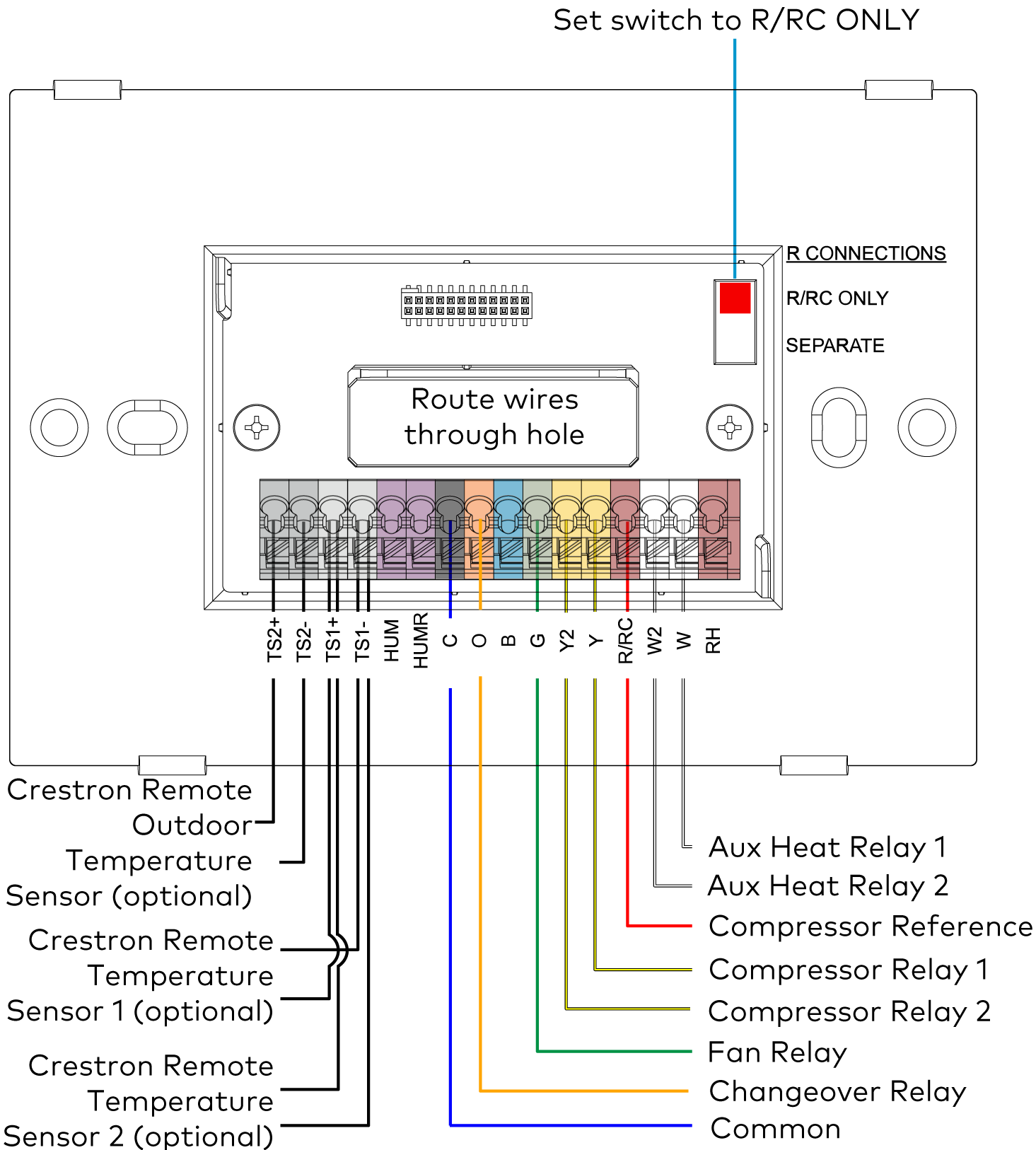
Wiring Diagrams
The image title is Wiring Diagrams, features dimensions of width 1465 px and height 1626 px, with a file size of 1465 x 1626. This image image/png type visual are source from docs.crestron.com.
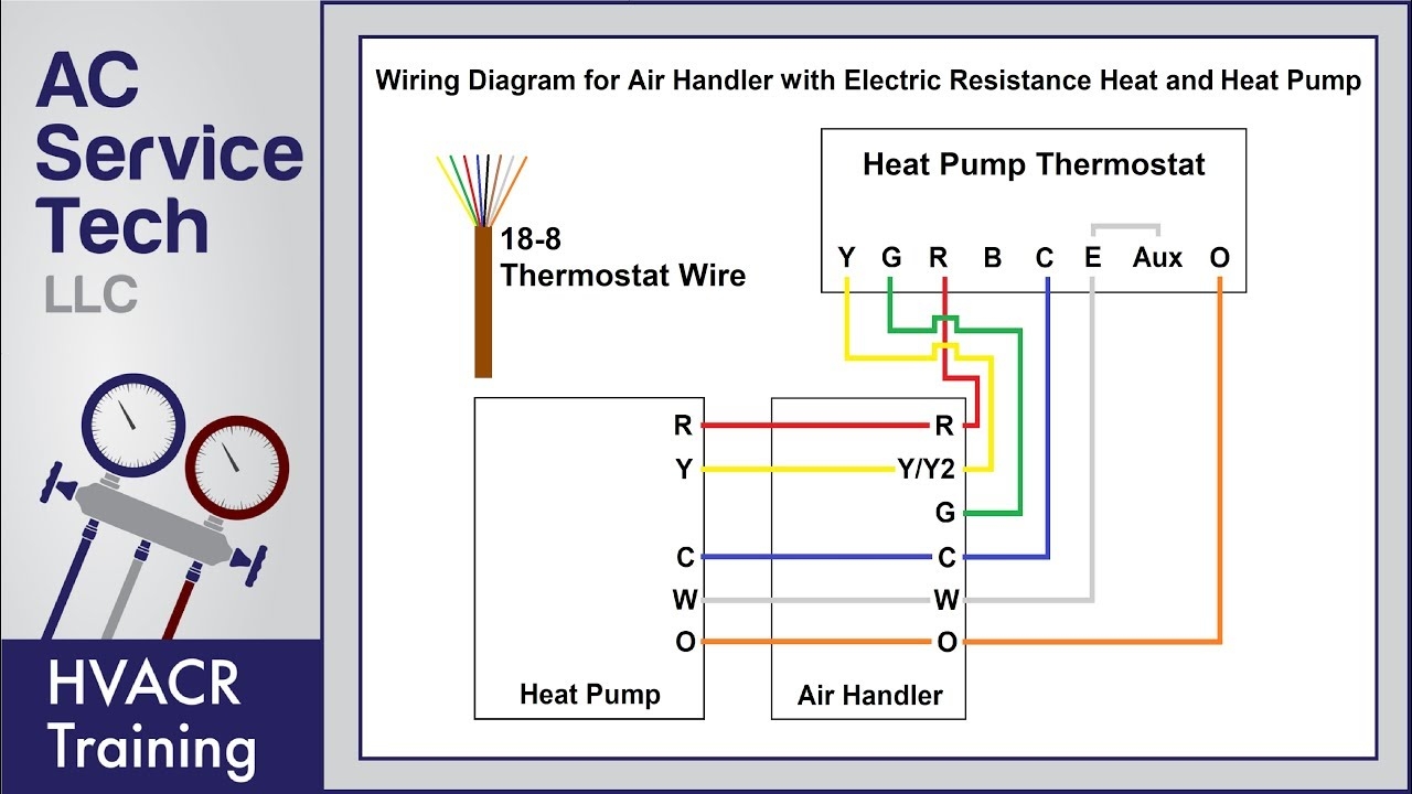
Heat Pump Thermostat Wiring Explained Colors Terminals Functions Circuit Path YouTube
The image title is Heat Pump Thermostat Wiring Explained Colors Terminals Functions Circuit Path YouTube, features dimensions of width 1280 px and height 720 px, with a file size of 1280 x 720.
The images on this page, sourced from Google for educational purposes, may be copyrighted. If you own an image and wish its removal or have copyright concerns, please contact us. We aim to promptly address these issues in compliance with our copyright policy and DMCA standards. Your cooperation is appreciated.
Related Keywords to Wiring Diagram For Heat Pump:
ecobee wiring diagram for heat pump,lennox wiring diagram for heat-pump,nest wiring diagram for heat pump,wiring diagram for goodman heat pump,wiring diagram for heat pump
