Table of Contents
Exploring the Value of Wiring Diagram For Air Handler
Exploring the Value of Wiring Diagram For Air Handler
When it comes to understanding the intricate workings of an air handler system, having a comprehensive wiring diagram is a crucial piece of the puzzle. A wiring diagram serves as a roadmap, guiding technicians and DIY enthusiasts alike through the complex network of electrical connections within an air handler unit. By providing a visual representation of how each component is linked together, a wiring diagram streamlines the troubleshooting process, ensures proper installation, and helps in identifying potential issues quickly and accurately. Let’s delve into the importance and utility of a wiring diagram for an air handler system, shedding light on its significance in maintaining optimal functionality.
The Basics of Wiring Diagram For Air Handler
A wiring diagram for an air handler is a detailed illustration that depicts the electrical connections between various components such as the blower motor, heating elements, thermostat, and control board. It showcases the path of electricity flow, highlighting the wiring configuration and color-coding for easy identification. This visual representation simplifies the troubleshooting process by enabling technicians to pinpoint faulty connections, diagnose issues, and perform repairs with precision. Whether you are installing a new air handler unit or troubleshooting an existing one, referring to a wiring diagram is instrumental in ensuring a smooth and efficient operation.
The Benefits of Using a Wiring Diagram
Enhanced Troubleshooting: A wiring diagram provides a clear overview of the electrical connections, making it easier to troubleshoot issues and identify faulty components.
Accurate Installation: By following the wiring diagram, installers can ensure that each component is connected correctly, preventing potential hazards from improper wiring.
Time-Saving Solution: Having a wiring diagram on hand saves time during maintenance and repairs, as technicians can quickly locate the source of the problem without guesswork.
Preventative Maintenance: Regularly referencing the wiring diagram allows for proactive maintenance, helping to detect issues early and prevent costly repairs down the line.
Understanding the Components in a Wiring Diagram
A typical wiring diagram for an air handler includes components such as the transformer, relay, capacitor, fan motor, and various switches. Each component is represented by specific symbols and color codes, indicating their function and connection points within the system. Understanding these components and their interactions is essential for interpreting the wiring diagram correctly and ensuring the proper functioning of the air handler unit.
Interpreting Color Codes in a Wiring Diagram
Red: Typically represents power supply lines or connections to heating elements.
Blue: Often used for cooling-related components such as the blower motor or compressor.
Yellow: Indicates connections to the thermostat or control board for temperature regulation.
Green: Represents the grounding wire or connections to the fan motor for circulation.
By familiarizing yourself with these color codes and symbols, you can navigate through the wiring diagram with ease, ensuring that each connection is made correctly and functioning as intended.
Conclusion
In conclusion, a wiring diagram for an air handler is a valuable tool that simplifies the installation, maintenance, and troubleshooting of HVAC systems. By providing a visual guide to the electrical connections and components within the air handler unit, a wiring diagram enhances efficiency, accuracy, and safety in handling electrical systems. Whether you are a seasoned technician or a DIY enthusiast, having access to a comprehensive wiring diagram is essential for achieving optimal performance and longevity of your air handler system.
Related to Wiring Diagram For Air Handler
- Wiring Diagram For Ac Thermostat
- Wiring Diagram For Ac Unit
- Wiring Diagram For Ac Unit Thermostat
- Wiring Diagram For Aftermarket Stereo
- Wiring Diagram For Air Compressor Pressure Switch
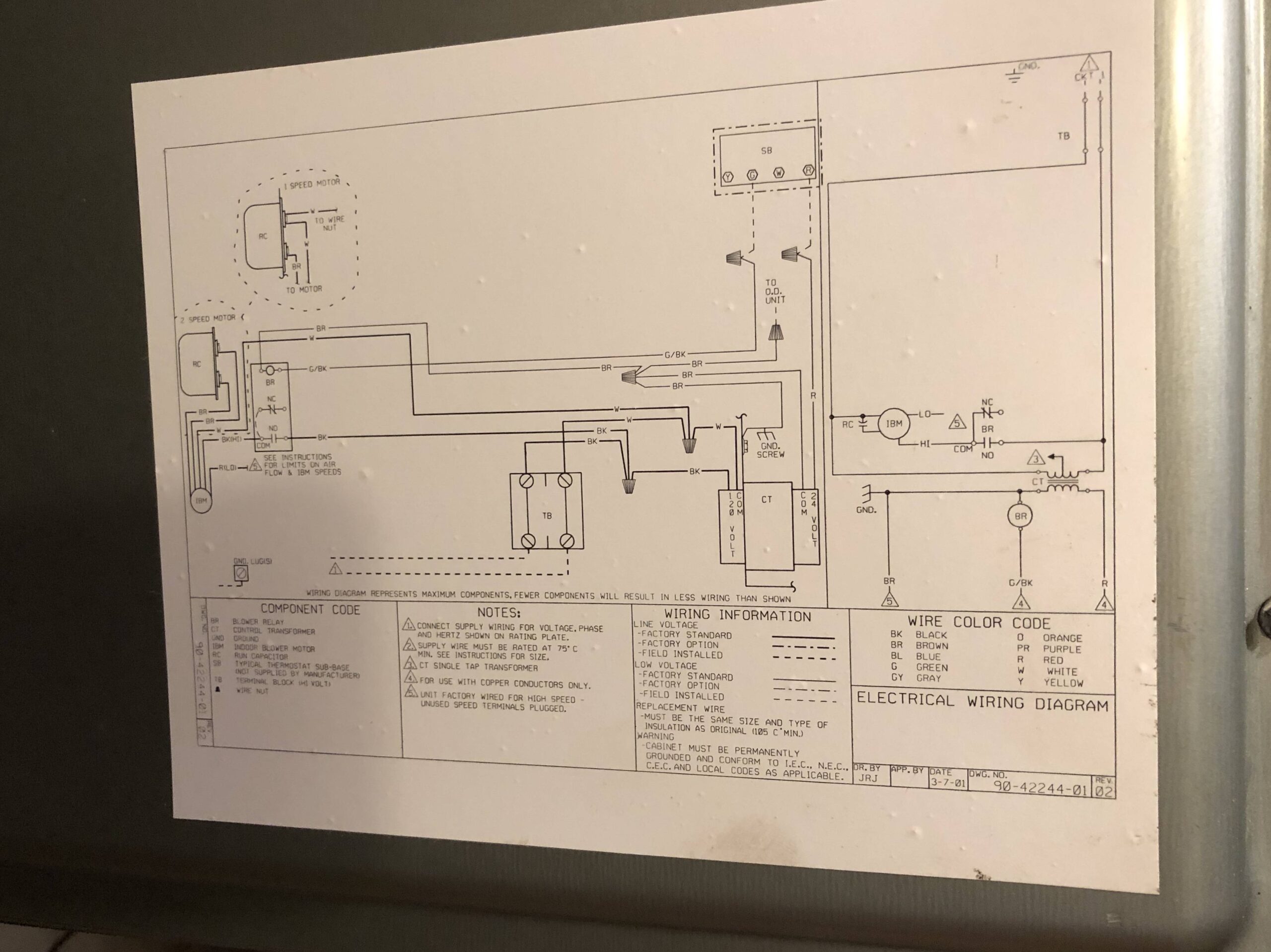
Hvac Common Wire Hookup In Air Handler Home Improvement Stack Exchange
The image title is Hvac Common Wire Hookup In Air Handler Home Improvement Stack Exchange, features dimensions of width 2560 px and height 1917 px, with a file size of 3816 x 2858 px. This image image/jpeg type visual are source from diy.stackexchange.com.
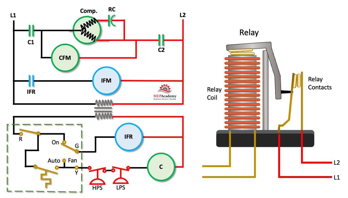
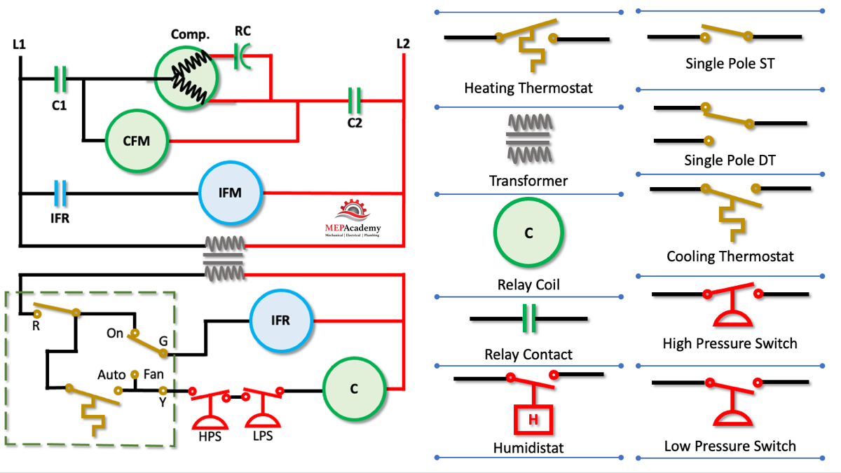
How To Read Wiring Diagrams In HVAC Systems MEP Academy
The image title is How To Read Wiring Diagrams In HVAC Systems MEP Academy, features dimensions of width 1200 px and height 685 px, with a file size of 1200 x 685 px. This image image/png type visual are source from mepacademy.com.
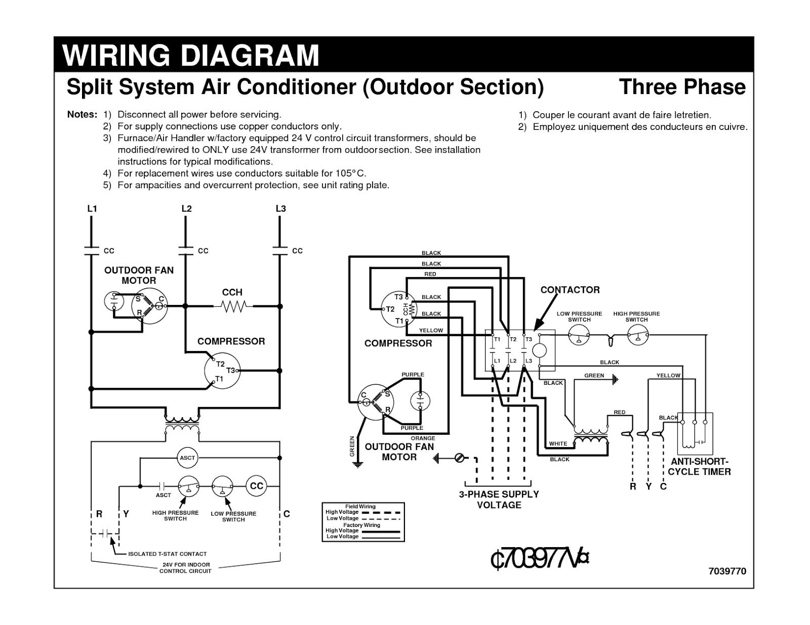
Electrical Wiring Diagrams For Air Conditioning Systems Part One Electrical Knowhow
The image title is Electrical Wiring Diagrams For Air Conditioning Systems Part One Electrical Knowhow, features dimensions of width 1600 px and height 1236 px, with a file size of 1600 x 1236. This image image/png type visual are source from www.electrical-knowhow.com.
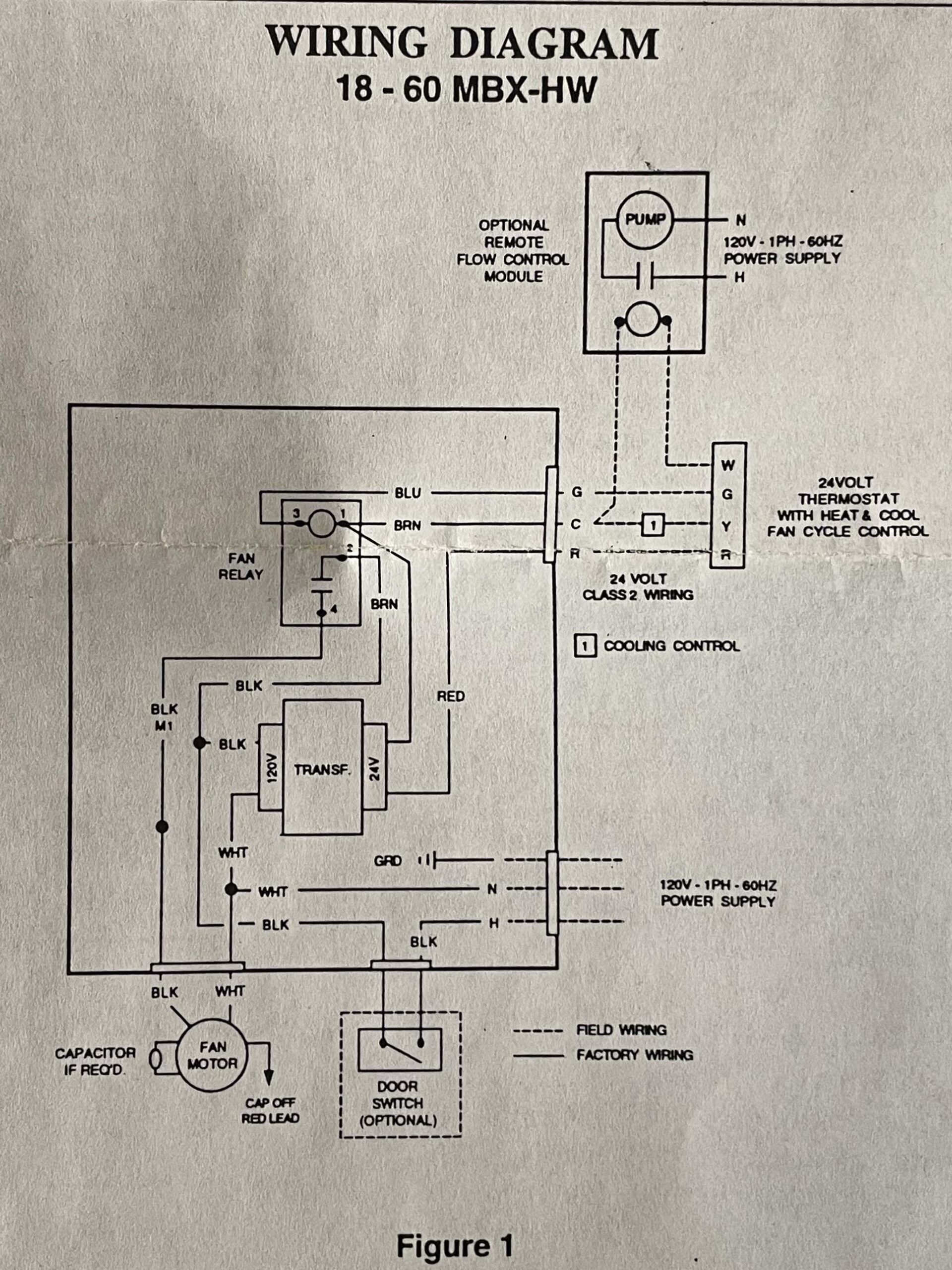
Hvac Where To Connect Common Wire From Thermostat To First Co Air Handler Home Improvement Stack Exchange
The image title is Hvac Where To Connect Common Wire From Thermostat To First Co Air Handler Home Improvement Stack Exchange, features dimensions of width 1920 px and height 2560 px, with a file size of 1935 x 2580. This image image/jpeg type visual are source from diy.stackexchange.com.
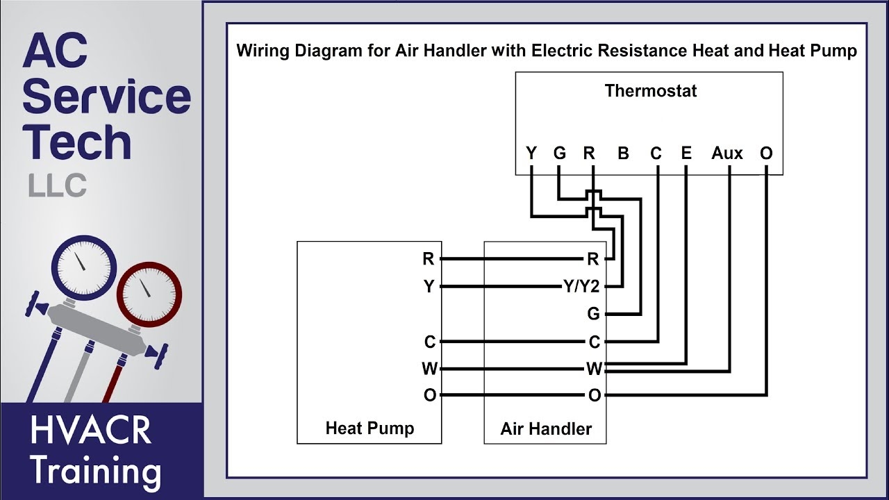
Thermostat Wiring Diagrams 10 Most Common YouTube
The image title is Thermostat Wiring Diagrams 10 Most Common YouTube, features dimensions of width 1280 px and height 720 px, with a file size of 1280 x 720. This image image/jpeg type visual are source from m.youtube.com
How To Read Wiring Diagrams In HVAC Systems MEP Academy
The image title is How To Read Wiring Diagrams In HVAC Systems MEP Academy, features dimensions of width 1200 px and height 675 px, with a file size of 1200 x 675. This image image/png type visual are source from mepacademy.com.
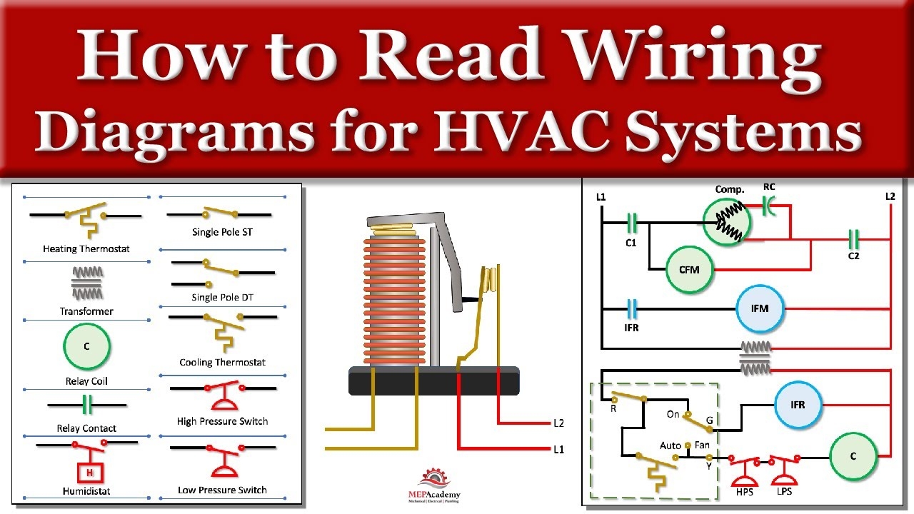
How To Read Wiring Diagrams For HVAC Equipment YouTube
The image title is How To Read Wiring Diagrams For HVAC Equipment YouTube, features dimensions of width 1280 px and height 720 px, with a file size of 1280 x 720. This image image/jpeg type visual are source from m.youtube.com.
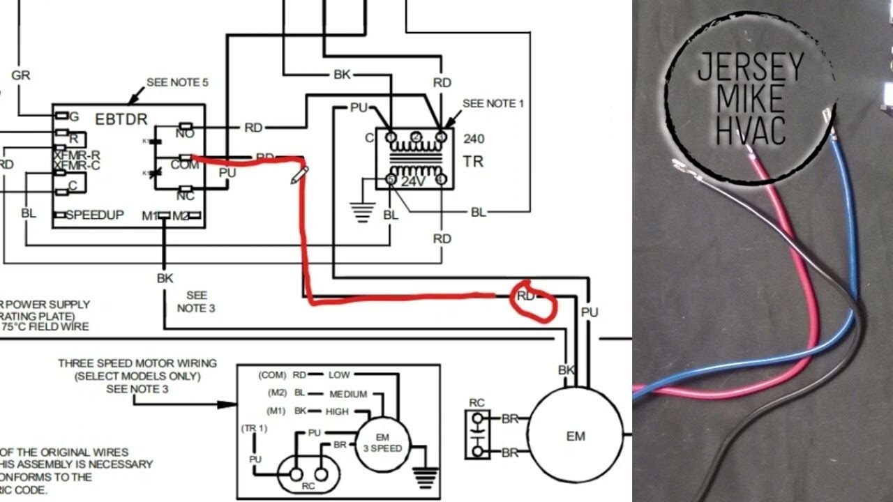
Air Handler Wiring For Beginners Fan Relays PSC Motors YouTube
The image title is Air Handler Wiring For Beginners Fan Relays PSC Motors YouTube, features dimensions of width 1280 px and height 720 px, with a file size of 1280 x 720.
The images on this page, sourced from Google for educational purposes, may be copyrighted. If you own an image and wish its removal or have copyright concerns, please contact us. We aim to promptly address these issues in compliance with our copyright policy and DMCA standards. Your cooperation is appreciated.
Related Keywords to Wiring Diagram For Air Handler:
wiring diagram for air conditioner,wiring diagram for air conditioner capacitor,wiring diagram for air conditioner thermostat,wiring diagram for air handler,wiring diagram for goodman air handler
