Table of Contents
The Power of a Wiring Diagram For A Contactor
When it comes to electrical systems, precision and accuracy are paramount. A wiring diagram for a contactor serves as a crucial tool in ensuring that electrical circuits are correctly connected and functioning as intended. This detailed schematic provides a visual representation of the wiring layout, allowing electricians and technicians to understand the relationships between various components and troubleshoot any issues effectively.
Understanding the Components
Before delving into the intricacies of a wiring diagram for a contactor, it is essential to grasp the primary components involved in the circuit. A contactor is an electrical relay that controls the flow of electricity to a load, such as a motor or lighting system. It consists of contacts, coils, and an enclosure to protect the internal components from environmental factors.
Interpreting the Wiring Diagram
A wiring diagram for a contactor typically includes symbols and labels that represent the different elements within the circuit. These symbols indicate the connections between the contactor, power source, control devices, and the load. By deciphering these symbols and following the designated wiring paths, technicians can ensure that the electrical system operates safely and efficiently.
Benefits of Utilizing a Wiring Diagram
The use of a wiring diagram for a contactor offers numerous advantages in the field of electrical work. By referring to this visual aid, technicians can:
- Ensure proper installation and connection of components
- Troubleshoot electrical faults quickly and accurately
- Maintain consistency in wiring practices for standardized procedures
- Enhance safety measures by adhering to industry regulations
Implementation in Real-World Scenarios
In practical applications, a wiring diagram for a contactor proves invaluable during new installations, repairs, or upgrades to electrical systems. By following the guidelines outlined in the diagram, technicians can streamline their workflow, minimize errors, and optimize the performance of the circuit. Whether working on industrial machinery, HVAC systems, or commercial lighting fixtures, having a clear and detailed wiring diagram is essential for achieving optimal results.
Conclusion
In conclusion, a wiring diagram for a contactor serves as a foundational tool in the realm of electrical engineering and maintenance. By understanding the value of this schematic and utilizing it effectively, technicians can navigate complex electrical circuits with confidence and precision. Whether it’s ensuring compliance with safety standards or enhancing operational efficiency, the use of a wiring diagram empowers professionals to tackle electrical challenges with ease.
Related to Wiring Diagram For A Contactor
- Wiring Diagram For A Bathroom
- Wiring Diagram For A Bedroom
- Wiring Diagram For A Boat Trailer
- Wiring Diagram For A Camper Trailer
- Wiring Diagram For A Capacitor
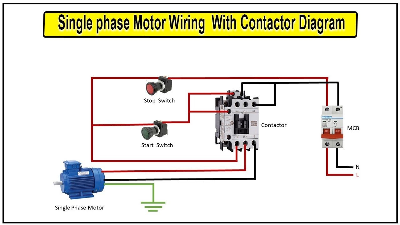
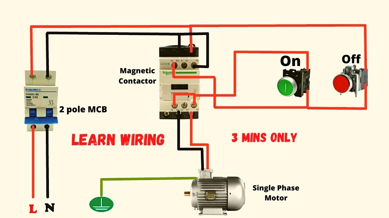
How To Make Single Phase Motor Wiring With Contactor Diagram Motor Switch House House Wiring Wire
The image title is How To Make Single Phase Motor Wiring With Contactor Diagram Motor Switch House House Wiring Wire, features dimensions of width 1280 px and height 720 px, with a file size of 1280 x 720 px. This image image/jpeg type visual are source from www.pinterest.com.
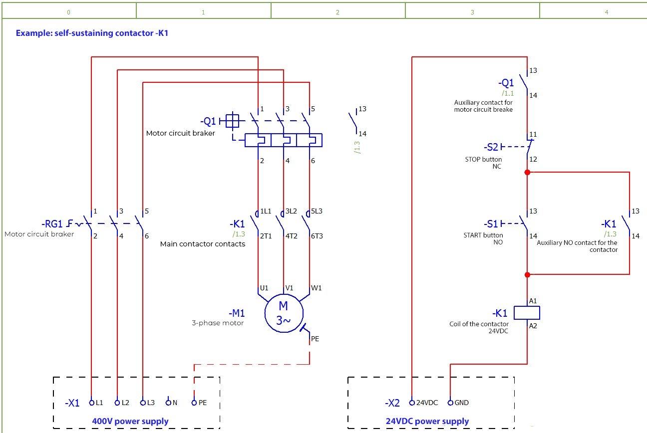
Electrical Symbols How To Read Electrical Schematics 3 CONTACTORS Blog Related To Industrial Automation PLC HMI Control Systems
The image title is Electrical Symbols How To Read Electrical Schematics 3 CONTACTORS Blog Related To Industrial Automation PLC HMI Control Systems, features dimensions of width 1296 px and height 868 px, with a file size of 1296 x 868 px. This image image/jpeg type visual are source from automationtop.com.
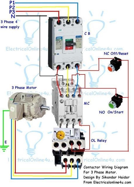
Contactor Wiring Guide For 3 Phase Motor With Circuit Breaker Overload Relay NC NO Switches Home Electrical Wiring Basic Electrical Wiring Electrical Wiring
The image title is Contactor Wiring Guide For 3 Phase Motor With Circuit Breaker Overload Relay NC NO Switches Home Electrical Wiring Basic Electrical Wiring Electrical Wiring, features dimensions of width 459 px and height 640 px, with a file size of 459 x 640. This image image/jpeg type visual are source from www.pinterest.com.
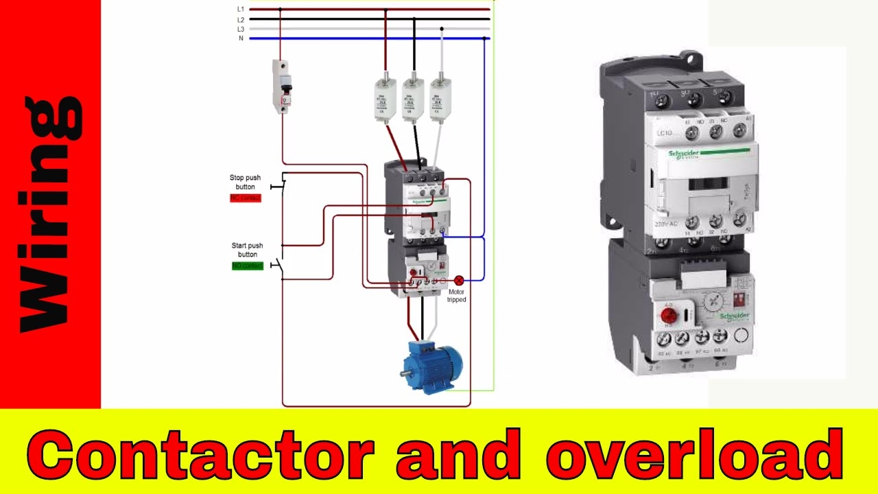
How To Wire A Contactor And Overload Direct Online Starter YouTube
The image title is How To Wire A Contactor And Overload Direct Online Starter YouTube, features dimensions of width 1280 px and height 720 px, with a file size of 1280 x 720. This image image/jpeg type visual are source from www.youtube.com.
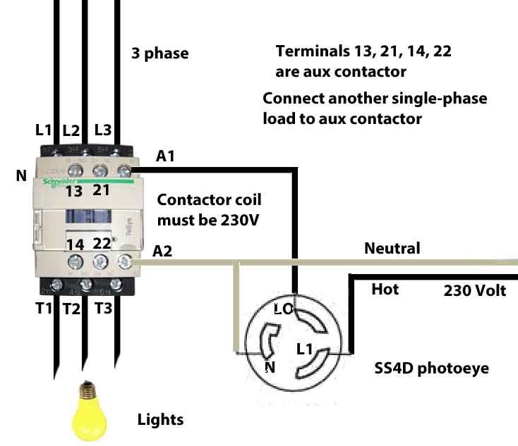
How To Wire Motor Control Contactor
The image title is How To Wire Motor Control Contactor, features dimensions of width 734 px and height 633 px, with a file size of 734 x 633. This image image/jpeg type visual are source from waterheatertimer.org
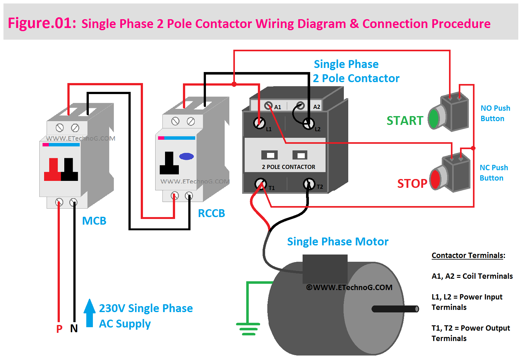
Single Phase 2 Pole Contactor Wiring Diagram Electrical Diagram Electrical Circuit Diagram Pole
The image title is Single Phase 2 Pole Contactor Wiring Diagram Electrical Diagram Electrical Circuit Diagram Pole, features dimensions of width 1661 px and height 1157 px, with a file size of 1661 x 1157. This image image/png type visual are source from www.pinterest.com.
Single Phase Motor Connection With Magnetic Contactor Wiring Diagram YouTube
The image title is Single Phase Motor Connection With Magnetic Contactor Wiring Diagram YouTube, features dimensions of width 1280 px and height 720 px, with a file size of 1280 x 720. This image image/jpeg type visual are source from www.youtube.com.
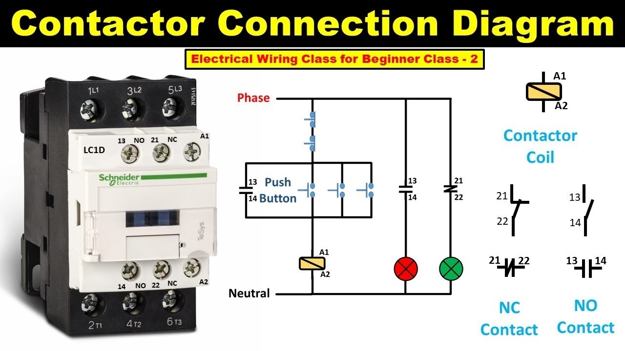
How To Do Contactor Wiring Electrical Wiring Class For Beginner Class 2 TheElectricalGuy YouTube
The image title is How To Do Contactor Wiring Electrical Wiring Class For Beginner Class 2 TheElectricalGuy YouTube, features dimensions of width 1280 px and height 720 px, with a file size of 1280 x 720.
The images on this page, sourced from Google for educational purposes, may be copyrighted. If you own an image and wish its removal or have copyright concerns, please contact us. We aim to promptly address these issues in compliance with our copyright policy and DMCA standards. Your cooperation is appreciated.
Related Keywords to Wiring Diagram For A Contactor:
wiring diagram for a contactor,wiring diagram for ac contactor,wiring diagram for contactor and overload,wiring diagram for contactor and photocell,wiring diagram for magnetic contactor
