Table of Contents
The Importance of Wiring Diagrams
When it comes to understanding the intricate network of electrical connections within a system, a wiring diagram serves as a crucial tool. It provides a visual representation of how various components are connected, enabling technicians and DIY enthusiasts alike to troubleshoot issues, plan installations, and ensure that everything functions seamlessly. In the realm of complex machinery and electronic systems, having access to a comprehensive wiring diagram can make all the difference in achieving optimal performance and minimizing downtime.
Enhancing Efficiency and Accuracy
By offering a clear and detailed layout of the electrical pathways, a wiring diagram streamlines the process of identifying potential faults or areas of improvement. Whether you’re working on a vehicle, appliance, or industrial equipment, having a well-organized diagram at your disposal can significantly reduce the time spent diagnosing issues and carrying out repairs. This level of efficiency not only saves valuable time but also ensures that repairs or modifications are done with precision, minimizing the risk of errors or oversights.
Facilitating Collaboration and Communication
In a professional setting where multiple technicians or engineers may be involved in a project, a wiring diagram acts as a common language that ensures everyone is on the same page. By providing a visual reference that transcends language barriers or individual interpretations, it promotes effective collaboration and seamless communication among team members. This cohesion is essential for large-scale projects where the coordination of various electrical components is paramount to success.
Key Components of a Wiring Diagram
A typical wiring diagram includes essential elements such as symbols, color-coding, and labels to convey information about the connections between different components. These visual cues are designed to simplify the interpretation of complex electrical schematics and make it easier for users to grasp the overall layout at a glance. By breaking down the system into manageable segments and highlighting key points of interest, a well-designed wiring diagram enhances comprehension and ensures that critical details are not overlooked.
Utilizing Symbols and Color Codes
Symbols are a universal language in the realm of wiring diagrams, representing various electrical components such as resistors, capacitors, and switches. By using standardized symbols that are easily recognizable across different diagrams, users can quickly identify specific elements and understand their function within the system. Additionally, color-coding is often employed to differentiate between different types of connections or voltage levels, further enhancing the clarity and readability of the diagram.
Labeling and Documentation
Another crucial aspect of a wiring diagram is the inclusion of detailed labels and documentation that provide context and clarity to the overall layout. By labeling each component, wire, or connection point with relevant information such as part numbers, ratings, or descriptions, users can easily trace the pathway of electricity and make informed decisions regarding maintenance or modifications. This level of documentation not only aids in troubleshooting and repairs but also serves as a valuable reference for future upgrades or expansions.
Related to Wiring Diagram For A
- Wiring Diagram For 7 Pin Trailer Lights
- Wiring Diagram For 7 Pin Trailer Plug
- Wiring Diagram For 7 Pin Trailer Socket
- Wiring Diagram For 7 Way Trailer Connector
- Wiring Diagram For 7 Way Trailer Plug
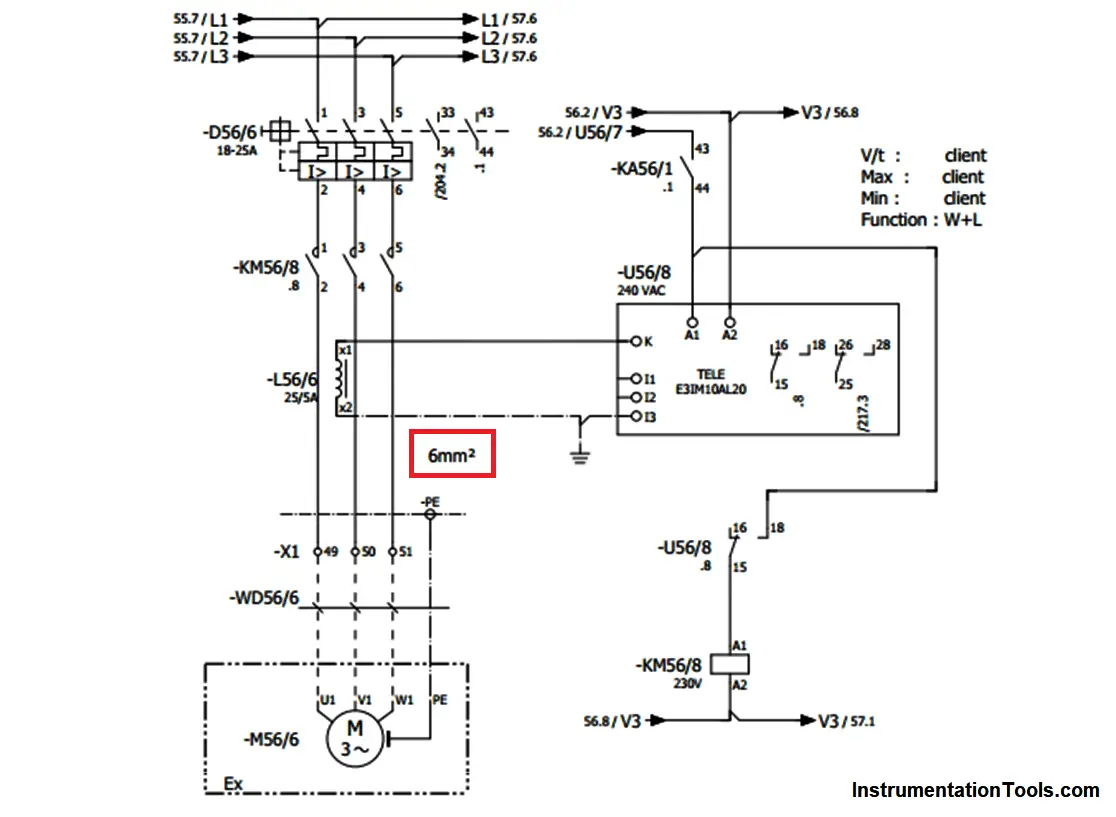
How To Read An Electrical Wiring Diagram Inst Tools
The image title is How To Read An Electrical Wiring Diagram Inst Tools, features dimensions of width 1116 px and height 817 px, with a file size of 1116 x 817 px. This image image/png type visual are source from instrumentationtools.com.
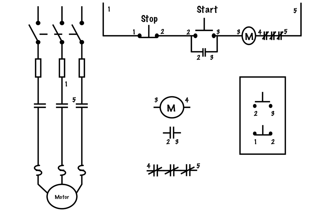
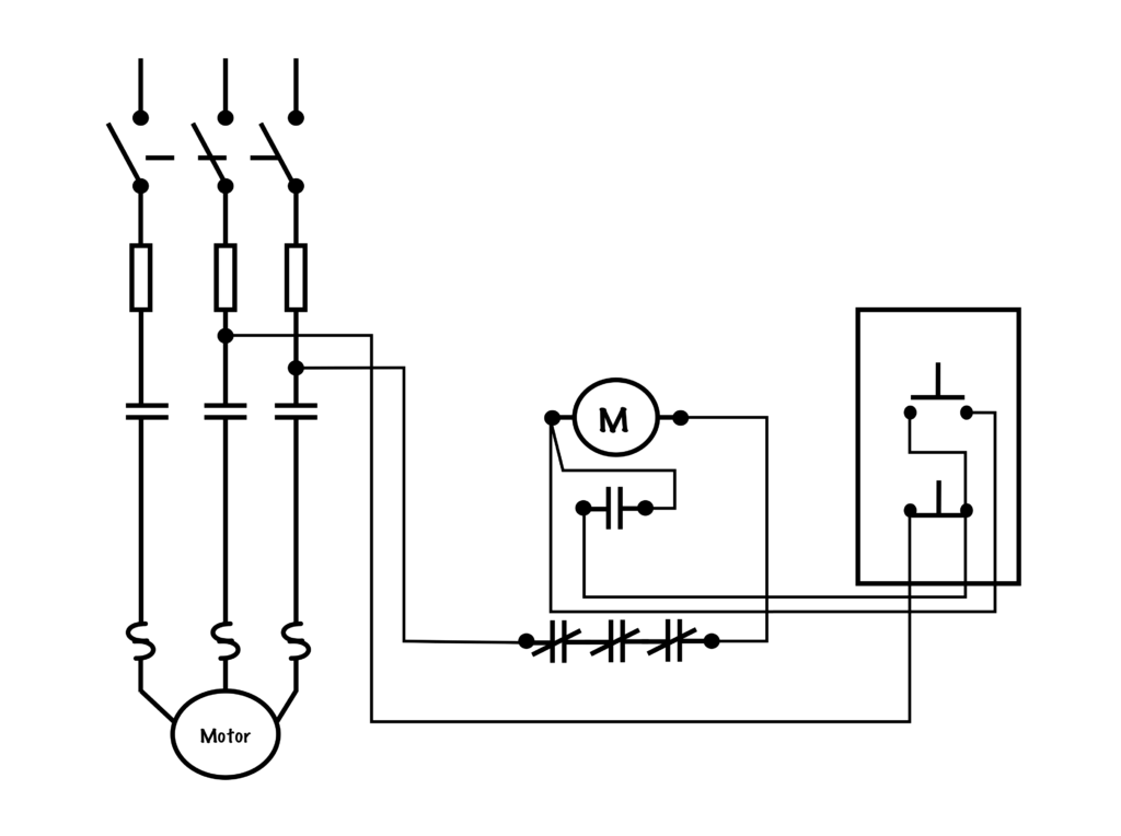
Transferring From Schematic To Wiring Diagram For Connection Purposes Basic Motor Control
The image title is Transferring From Schematic To Wiring Diagram For Connection Purposes Basic Motor Control, features dimensions of width 1024 px and height 695 px, with a file size of 1024 x 695 px. This image image/png type visual are source from opentextbc.ca.
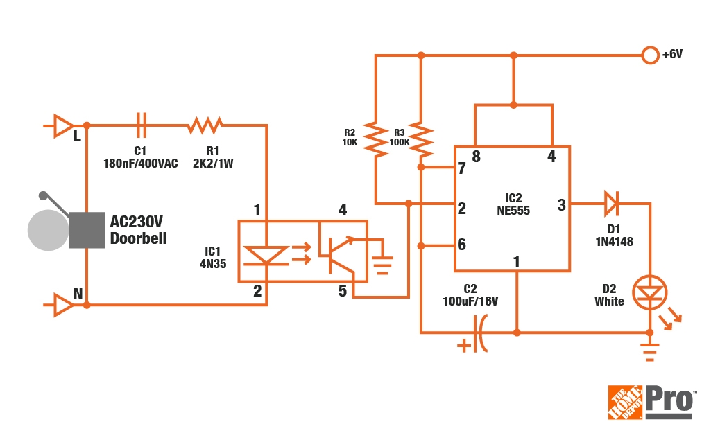
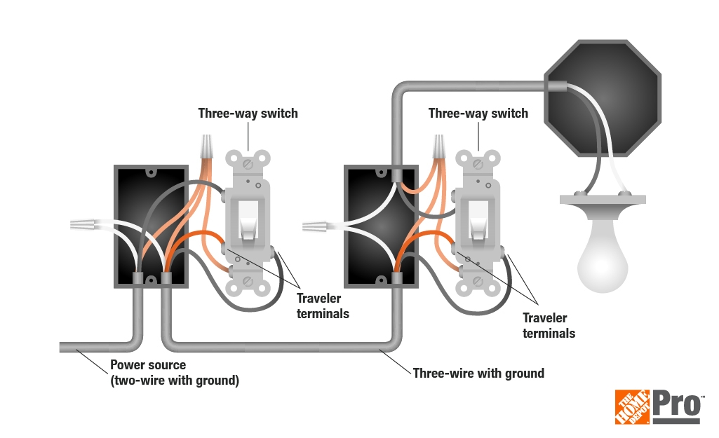
The 4 Types Of Wiring Diagrams The Home Depot
The image title is The 4 Types Of Wiring Diagrams The Home Depot, features dimensions of width 1025 px and height 625 px, with a file size of 1025 x 625. This image image/jpeg type visual are source from www.homedepot.com.
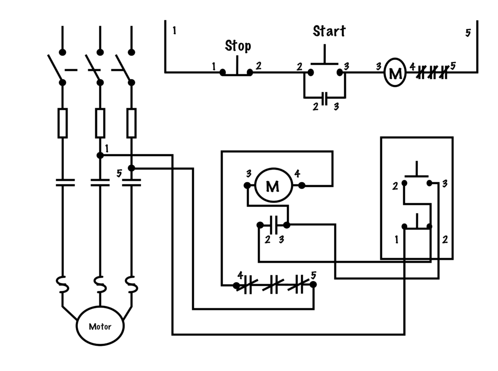
Transferring From Schematic To Wiring Diagram For Connection Purposes Basic Motor Control
The image title is Transferring From Schematic To Wiring Diagram For Connection Purposes Basic Motor Control, features dimensions of width 1024 px and height 764 px, with a file size of 1024 x 764. This image image/png type visual are source from opentextbc.ca.
The 4 Types Of Wiring Diagrams The Home Depot
The image title is The 4 Types Of Wiring Diagrams The Home Depot, features dimensions of width 1025 px and height 625 px, with a file size of 1025 x 625. This image image/jpeg type visual are source from www.homedepot.com
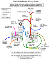
Wiring Diagram Wikipedia
The image title is Wiring Diagram Wikipedia, features dimensions of width 170 px and height 201 px, with a file size of 170 x 201. This image image/png type visual are source from en.wikipedia.org.
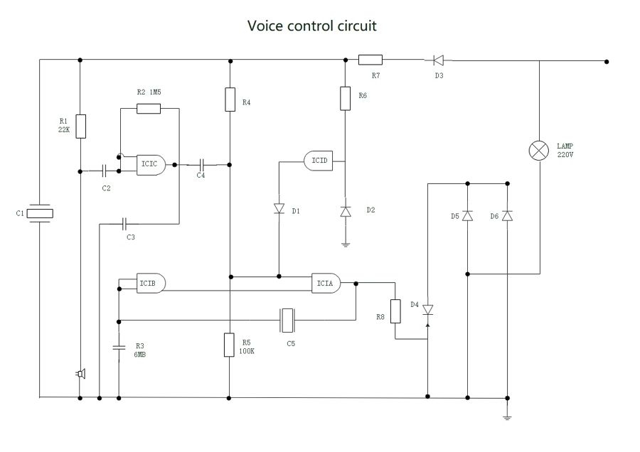
Wiring Diagram Definition How To Create Free Examples EdrawMax
The image title is Wiring Diagram Definition How To Create Free Examples EdrawMax, features dimensions of width 900 px and height 636 px, with a file size of 900 x 636. This image image/jpeg type visual are source from www.edrawsoft.com.
Schematic Vs Wiring Diagrams Basic Motor Control
The image title is Schematic Vs Wiring Diagrams Basic Motor Control, features dimensions of width 1024 px and height 764 px, with a file size of 1024 x 764.
The images on this page, sourced from Google for educational purposes, may be copyrighted. If you own an image and wish its removal or have copyright concerns, please contact us. We aim to promptly address these issues in compliance with our copyright policy and DMCA standards. Your cooperation is appreciated.
Related Keywords to Wiring Diagram For A:
wiring diagram for a,wiring diagram for a 3 way switch,wiring diagram for a light switch,wiring diagram for a trailer,wiring diagram for a trailer plug
