Table of Contents
The Value of Wiring Diagram Capacitor: A Comprehensive Guide
The Value of Wiring Diagram Capacitor
Wiring diagram capacitor is a crucial aspect of electrical systems that often gets overlooked. However, understanding the intricacies of capacitor wiring can greatly benefit both novices and seasoned professionals in the field. By delving into the world of wiring diagrams for capacitors, you can uncover a wealth of knowledge that will not only enhance your understanding of electrical circuits but also streamline your troubleshooting processes. Let’s explore the importance of wiring diagram capacitor and how it can elevate your expertise in the realm of electrical engineering.
The Basics of Capacitor Wiring
Before we dive into the specifics of wiring diagram capacitor, it’s essential to grasp the fundamentals of capacitor wiring. Capacitors are electronic components that store electrical energy and release it when needed. They play a vital role in smoothing out voltage fluctuations, filtering noise, and improving power factor correction in electrical circuits. Understanding how capacitors are wired in a circuit is crucial for ensuring optimal performance and safety.
Types of Capacitors
There are various types of capacitors used in electrical systems, each with its unique characteristics and applications. Common types of capacitors include electrolytic capacitors, ceramic capacitors, and tantalum capacitors. Different capacitor types have specific wiring requirements, so it’s essential to consult the wiring diagram capacitor for the particular type you are working with.
Importance of Wiring Diagrams
Wiring diagrams for capacitors provide a visual representation of how capacitors should be connected in a circuit. These diagrams detail the terminals, connections, and polarity of capacitors, ensuring that they are wired correctly to prevent malfunctions or damage. By following the wiring diagram capacitor, you can troubleshoot issues more efficiently and ensure the proper functioning of electrical systems.
Common Wiring Configurations
Capacitors can be wired in various configurations depending on the circuit requirements and desired outcomes. Some common wiring configurations include series wiring, parallel wiring, and dual capacitor wiring. Understanding the differences between these configurations and following the corresponding wiring diagrams is essential for achieving the desired electrical performance.
Series Wiring
In series wiring, capacitors are connected end to end to increase the overall capacitance of the circuit. This configuration is often used to achieve higher capacitance values than a single capacitor can provide. Following the series wiring diagram capacitor is crucial to ensure that the capacitors are connected in the correct sequence for optimal performance.
Parallel Wiring
Parallel wiring involves connecting capacitors side by side to share the voltage across them. This configuration is commonly used to increase the total capacitance while maintaining the voltage rating of each individual capacitor. By referencing the parallel wiring diagram capacitor, you can ensure that the connections are made correctly to prevent overloading or damaging the capacitors.
Dual Capacitor Wiring
Dual capacitor wiring is used in HVAC systems to power both the fan motor and compressor. This wiring configuration combines two capacitors into one unit, providing the necessary capacitance for both components. Following the dual capacitor wiring diagram capacitor is essential for proper installation and operation of HVAC systems.
Conclusion
In conclusion, understanding wiring diagram capacitor is essential for anyone working with electrical systems. By familiarizing yourself with capacitor wiring basics, different types of capacitors, and common wiring configurations, you can enhance your expertise in electrical engineering and ensure the optimal performance of circuits. Remember to always consult the wiring diagram capacitor specific to the type of capacitor you are working with to avoid errors and ensure safety. Embrace the value of wiring diagram capacitor, and elevate your skills in the realm of electrical systems.
Related to Wiring Diagram Capacitor
- Wiring Diagram Bilge Pump
- Wiring Diagram Blower Motor
- Wiring Diagram Boat Trailer
- Wiring Diagram Brake Controller
- Wiring Diagram Campervan
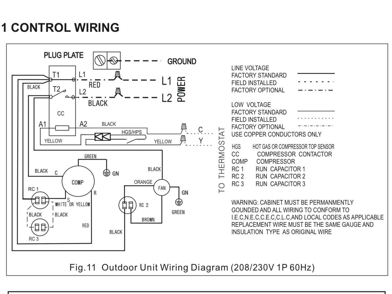
Wiring Can I Replace Two Run Capacitors With A Dual Run Capacitor Electrical Engineering Stack Exchange
The image title is Wiring Can I Replace Two Run Capacitors With A Dual Run Capacitor Electrical Engineering Stack Exchange, features dimensions of width 1560 px and height 1170 px, with a file size of 1560 x 1170 px. This image image/jpeg type visual are source from electronics.stackexchange.com.
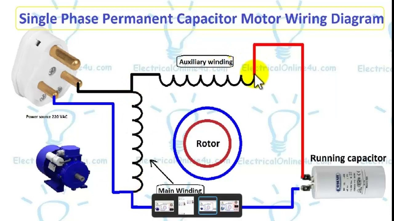
Single Phase Permanent Capacitor Motor Wiring Diagram English YouTube
The image title is Single Phase Permanent Capacitor Motor Wiring Diagram English YouTube, features dimensions of width 1280 px and height 720 px, with a file size of 1280 x 720 px. This image image/jpeg type visual are source from m.youtube.com.
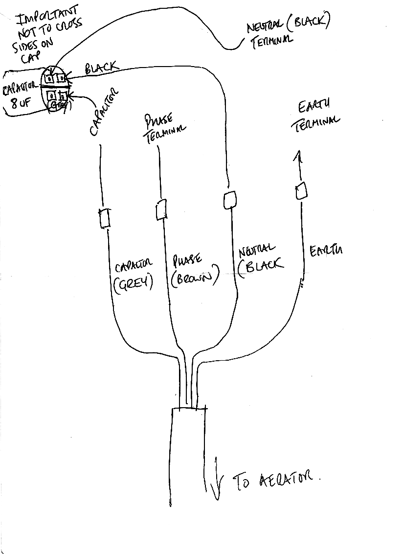
Help Understanding Wiring Of Capacitor Electrical Engineering Stack Exchange
The image title is Help Understanding Wiring Of Capacitor Electrical Engineering Stack Exchange, features dimensions of width 824 px and height 1132 px, with a file size of 824 x 1132. This image image/png type visual are source from electronics.stackexchange.com.
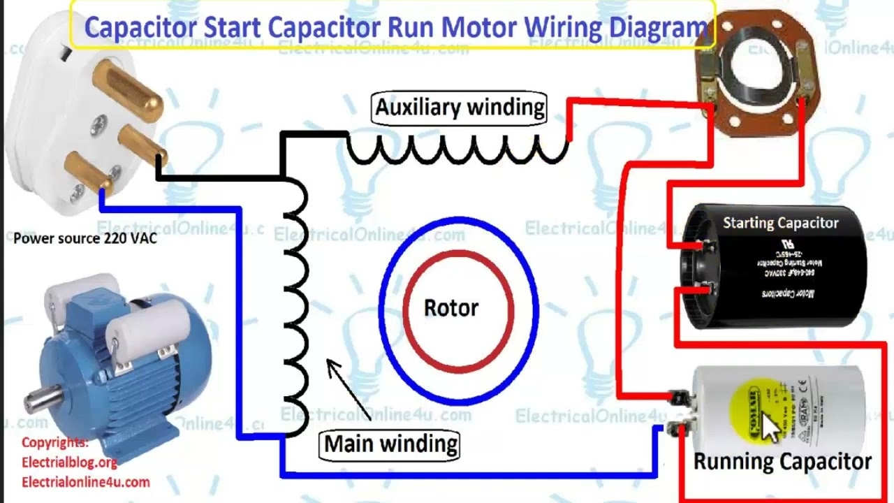
Single Phase Motor Wiring Diagram With Capacitor Start Capacitor Run English YouTube
The image title is Single Phase Motor Wiring Diagram With Capacitor Start Capacitor Run English YouTube, features dimensions of width 1280 px and height 720 px, with a file size of 1280 x 720. This image image/jpeg type visual are source from m.youtube.com.
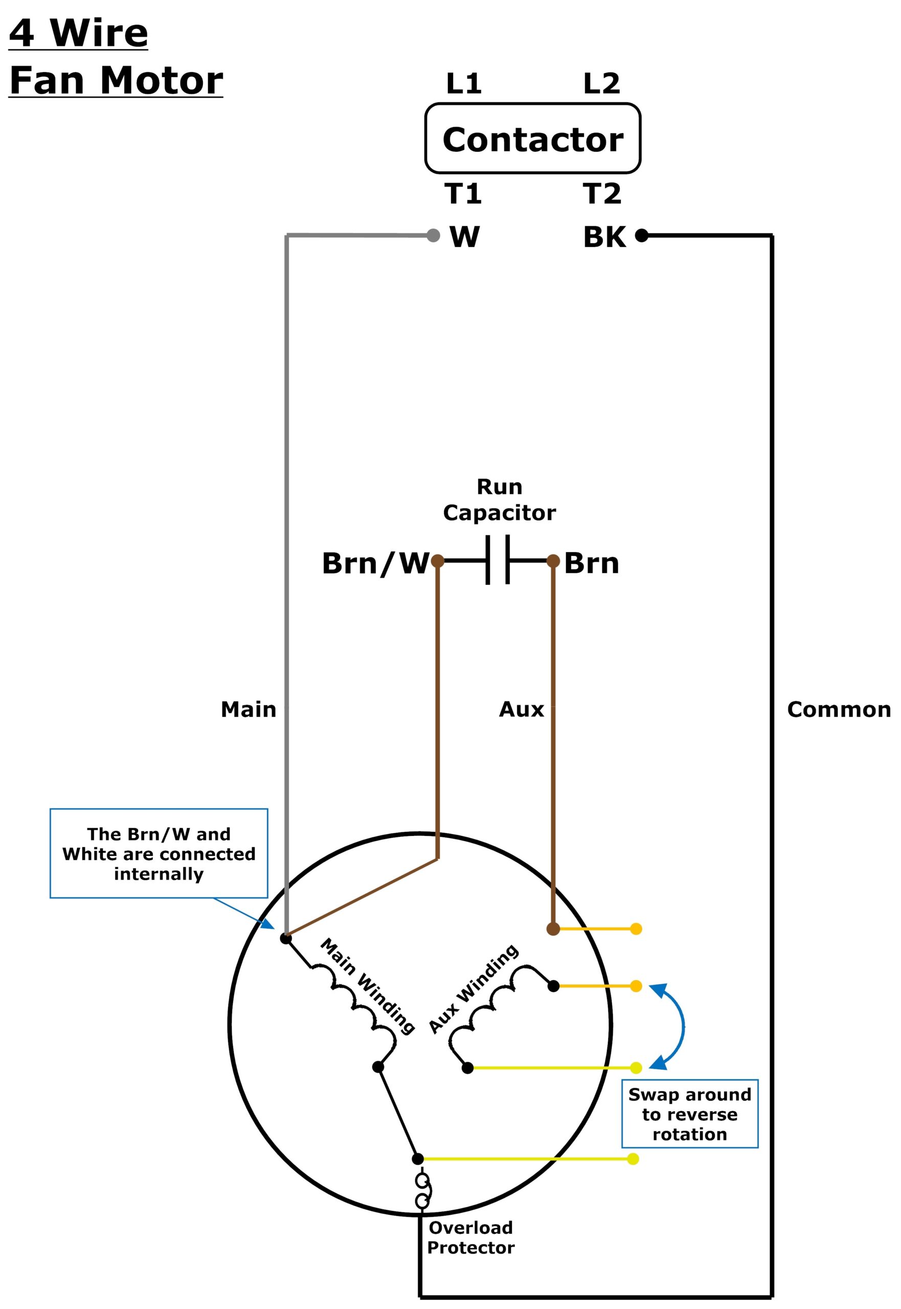
3 Or 4 Wire Condenser Fan Motor Wiring Johnstone Supply Support
The image title is 3 Or 4 Wire Condenser Fan Motor Wiring Johnstone Supply Support, features dimensions of width 1762 px and height 2560 px, with a file size of 2837 x 4123. This image image/jpeg type visual are source from support.johnstonehvac.biz
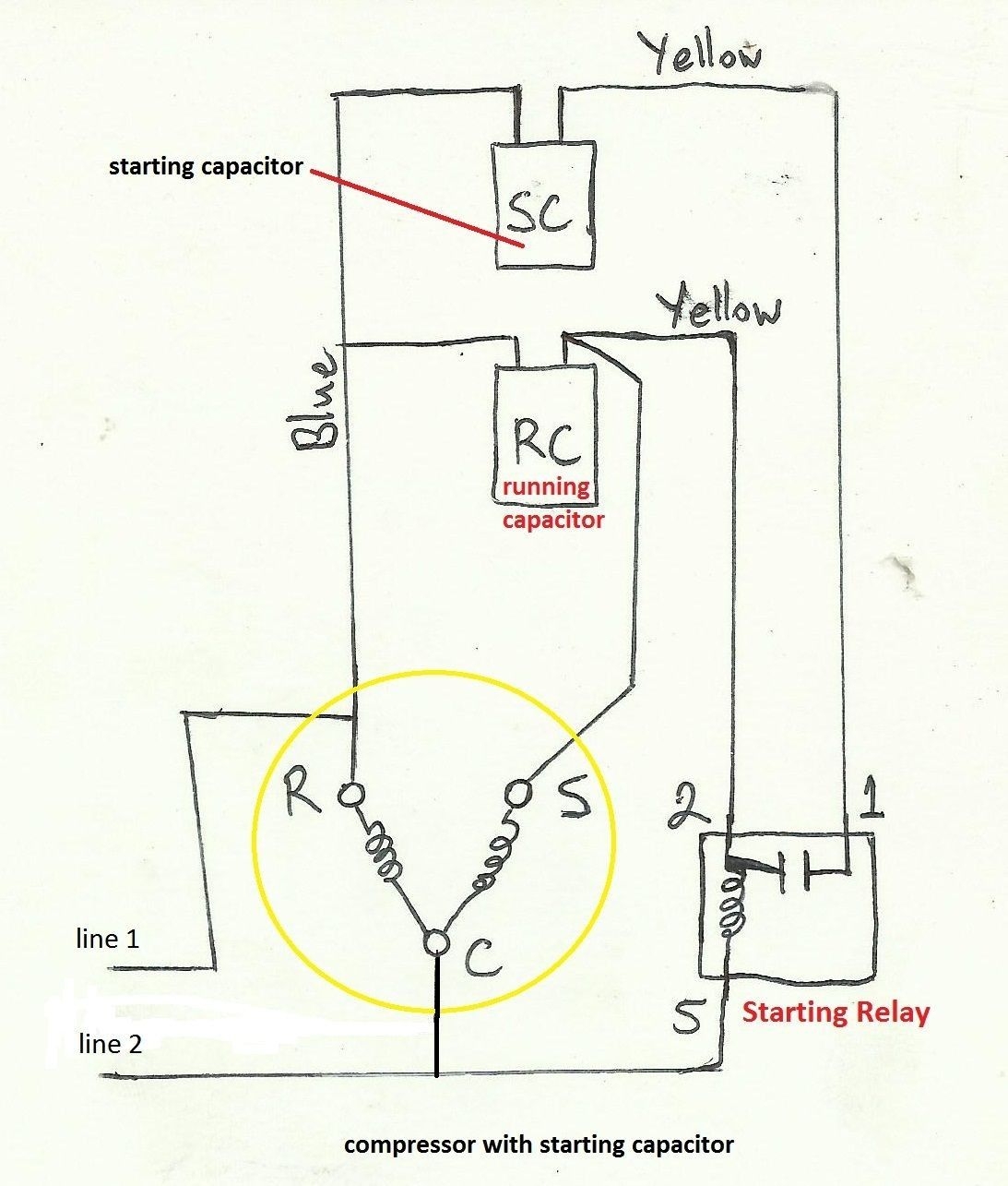
Awesome Refrigerator Compressor Relay Wiring Diagram Electrical Wiring Diagram Electrical Circuit Diagram Refrigeration And Air Conditioning
The image title is Awesome Refrigerator Compressor Relay Wiring Diagram Electrical Wiring Diagram Electrical Circuit Diagram Refrigeration And Air Conditioning, features dimensions of width 1093 px and height 1285 px, with a file size of 1093 x 1285. This image image/jpeg type visual are source from www.pinterest.com.
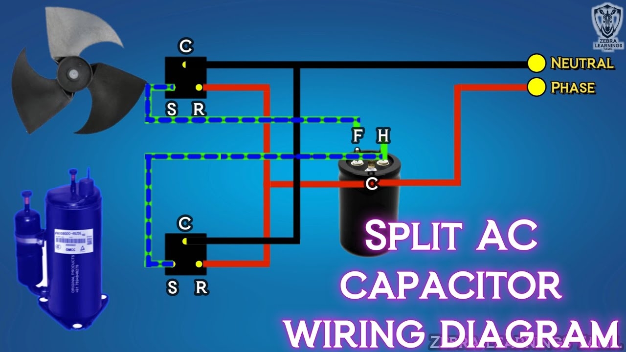
Split AC Capacitor Wiring Diagram Dual Capacitor HVAC Electrical YouTube
The image title is Split AC Capacitor Wiring Diagram Dual Capacitor HVAC Electrical YouTube, features dimensions of width 1280 px and height 720 px, with a file size of 1280 x 720. This image image/jpeg type visual are source from m.youtube.com.
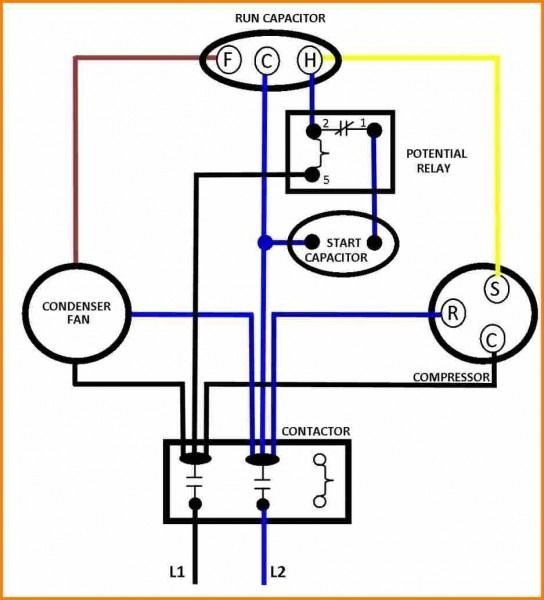
Capacitors For Compressor Wiring Diagram Ac Capacitor Hvac Compressor Air Compressor Motor
The image title is Capacitors For Compressor Wiring Diagram Ac Capacitor Hvac Compressor Air Compressor Motor, features dimensions of width 544 px and height 600 px, with a file size of 544 x 600.
The images on this page, sourced from Google for educational purposes, may be copyrighted. If you own an image and wish its removal or have copyright concerns, please contact us. We aim to promptly address these issues in compliance with our copyright policy and DMCA standards. Your cooperation is appreciated.
Related Keywords to Wiring Diagram Capacitor:
wiring diagram capacitor,wiring diagram capacitor bank,wiring diagram capacitor bank 3 phase,wiring diagram capacitor start motor,wiring diagram capacitor symbol
