Table of Contents
The Ultimate Guide to Voltage Regulator Wiring Diagram
Voltage regulator wiring diagram may sound like a complex topic at first glance, but understanding it can make a significant difference in various electrical applications. Whether you’re an experienced electrician or a DIY enthusiast, having a clear grasp of voltage regulator wiring diagrams is essential for ensuring the proper functioning of circuits and devices. In this comprehensive guide, we will delve into the intricacies of voltage regulator wiring diagrams, providing you with valuable insights and practical tips to navigate this crucial aspect of electrical systems.
The Basics of Voltage Regulator Wiring Diagram
Before we dive into the specifics of voltage regulator wiring diagrams, let’s start with the basics. A voltage regulator is a vital component in electrical circuits that maintains a steady output voltage regardless of fluctuations in input voltage or load conditions. By stabilizing the voltage levels, a voltage regulator ensures the safe operation of electronic devices and prevents damage due to overvoltage or undervoltage situations.
Types of Voltage Regulators
There are various types of voltage regulators, including linear regulators, switching regulators, and programmable regulators. Each type has its unique characteristics and applications, making it crucial to select the right regulator for a specific circuit or device.
- Linear Regulators: Known for their simplicity and low noise output, linear regulators are commonly used in low-power applications where efficiency is not a primary concern.
- Switching Regulators: Ideal for high-power applications due to their high efficiency and ability to step up or step down voltage levels, switching regulators are widely employed in modern electronic devices.
- Programmable Regulators: Offering flexibility and programmability, these regulators allow for dynamic adjustment of voltage levels, making them suitable for advanced applications requiring precise voltage control.
Understanding Voltage Regulator Wiring Diagrams
A voltage regulator wiring diagram illustrates the connection of components within a circuit, including the voltage regulator, input power source, output load, and other relevant elements. By following the wiring diagram, you can ensure that the voltage regulator is correctly integrated into the electrical system, minimizing the risk of malfunctions or damage.
Key Components in a Voltage Regulator Wiring Diagram
When examining a voltage regulator wiring diagram, it’s essential to identify the key components involved in the circuit. These components include:
- Input Power Source: The source of incoming voltage that the regulator regulates to provide a stable output.
- Output Load: The device or component that receives the regulated voltage from the regulator.
- Voltage Regulator: The core component responsible for maintaining a constant output voltage level.
- Feedback Mechanism: Circuitry that monitors the output voltage and provides feedback to the regulator for precise voltage regulation.
By understanding the roles of these components and how they are interconnected in a wiring diagram, you can troubleshoot issues, make modifications, or design new circuits with confidence.
Practical Tips for Voltage Regulator Wiring
To ensure a successful voltage regulator wiring process, consider the following practical tips:
- Verify the voltage requirements of the load and select a compatible regulator.
- Follow the manufacturer’s datasheet for the regulator to determine the pinout and wiring connections.
- Use appropriate wire gauges and connectors to handle the current and voltage levels in the circuit.
- Implement proper grounding and shielding techniques to minimize noise and interference.
By adhering to these tips and paying attention to detail in your wiring practices, you can ensure the reliability and efficiency of your voltage regulator circuits.
Conclusion
In conclusion, mastering the art of voltage regulator wiring diagrams is a valuable skill that can empower you to tackle a wide range of electrical projects with confidence. By understanding the principles behind voltage regulation, identifying key components in wiring diagrams, and implementing best practices in your wiring techniques, you can optimize the performance and longevity of your electronic devices.
Related to Voltage Regulator Wiring Diagram
- Vehicle Wiring Diagrams
- Vintage Air Wiring Diagram
- Viper Alarm Wiring Diagram
- Vista 20p Wiring Diagram
- Voltage Regulator Diagram Wiring
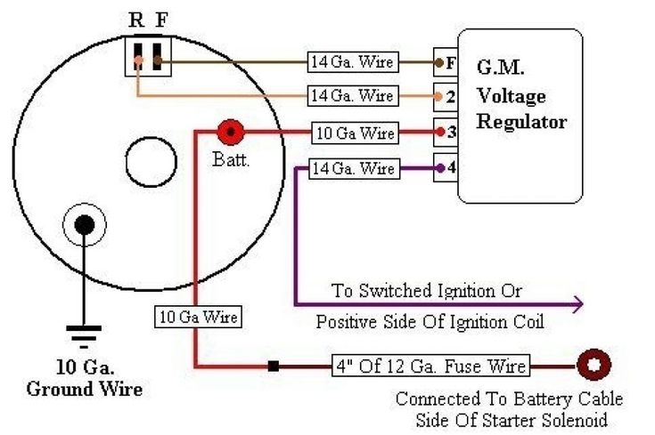
Typical Wiring Diagram Alternator And External Voltage Regulator Voltage Regulator Alternator Electrical Circuit Diagram
The image title is Typical Wiring Diagram Alternator And External Voltage Regulator Voltage Regulator Alternator Electrical Circuit Diagram, features dimensions of width 735 px and height 489 px, with a file size of 735 x 489 px. This image image/jpeg type visual are source from www.pinterest.es.
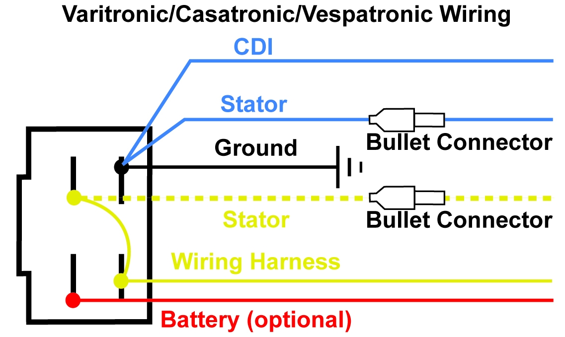
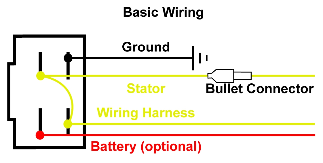
Regulator Wiring Diagrams
The image title is Regulator Wiring Diagrams, features dimensions of width 1137 px and height 679 px, with a file size of 1137 x 679 px. This image image/jpeg type visual are source from pistonported.com.
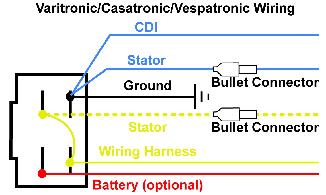
Regulator Wiring Diagrams
The image title is Regulator Wiring Diagrams, features dimensions of width 1137 px and height 679 px, with a file size of 1137 x 679. This image image/jpeg type visual are source from pistonported.com.
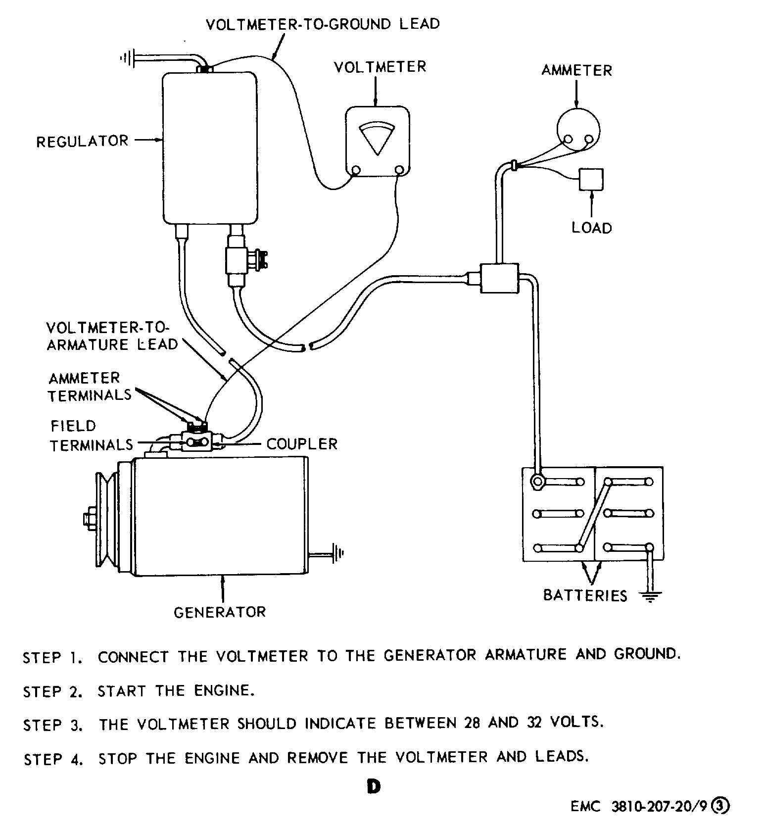
Figure 9 Generator Regulator Removal Adjustment And Test Wiring Diagram Cont TM 5 3810 207 20 65
The image title is Figure 9 Generator Regulator Removal Adjustment And Test Wiring Diagram Cont TM 5 3810 207 20 65, features dimensions of width 1544 px and height 1675 px, with a file size of 1544 x 1675. This image image/jpeg type visual are source from constructioncranes.tpub.com.
Regulator Wiring Diagrams
The image title is Regulator Wiring Diagrams, features dimensions of width 1122 px and height 567 px, with a file size of 1122 x 567. This image image/jpeg type visual are source from pistonported.com
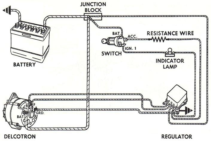
10DN The CJ2A Page Forums
The image title is 10DN The CJ2A Page Forums, features dimensions of width 705 px and height 473 px, with a file size of 705 x 473. This image image/jpeg type visual are source from www.thecj2apage.com.
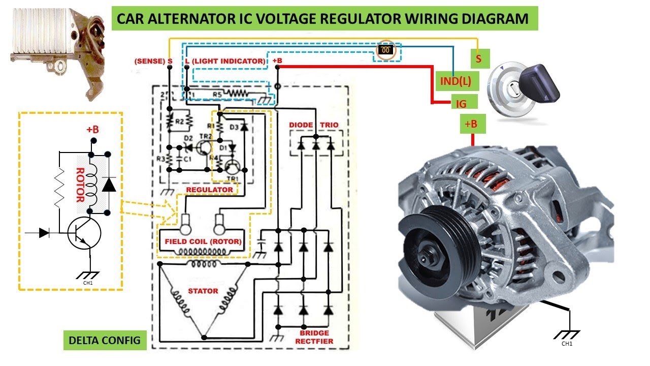
Car Alternator IC Voltage Regulator Wiring Diagram YouTube
The image title is Car Alternator IC Voltage Regulator Wiring Diagram YouTube, features dimensions of width 1280 px and height 720 px, with a file size of 1280 x 720. This image image/jpeg type visual are source from m.youtube.com.
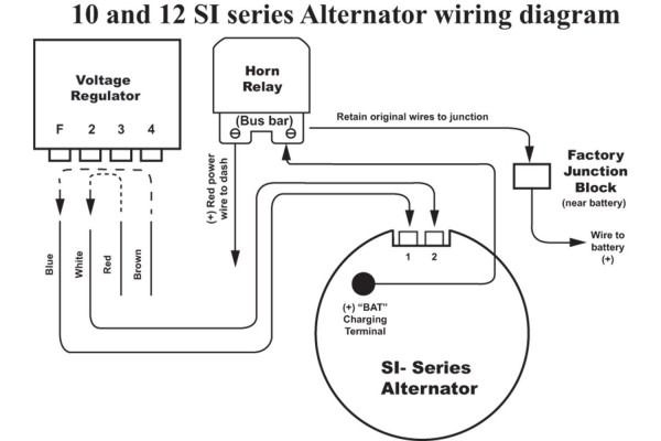
Typical Alternator Wiring Alternator Voltage Regulator Electrical Wiring Diagram
The image title is Typical Alternator Wiring Alternator Voltage Regulator Electrical Wiring Diagram, features dimensions of width 600 px and height 400 px, with a file size of 600 x 400.
The images on this page, sourced from Google for educational purposes, may be copyrighted. If you own an image and wish its removal or have copyright concerns, please contact us. We aim to promptly address these issues in compliance with our copyright policy and DMCA standards. Your cooperation is appreciated.
Related Keywords to Voltage Regulator Wiring Diagram:
voltage regulator circuit diagram,voltage regulator wiring diagram,voltage regulator wiring diagram ford,voltage regulator wiring diagram manual,voltage regulator wiring diagram motorcycle
