Table of Contents
Exploring the Trailer 7 Pin Connector Wiring Diagram
Welcome to the Ultimate Guide on Trailer 7 Pin Connector Wiring Diagram!
If you’ve ever been frustrated by the intricate wiring of your trailer’s 7 pin connector, fret not! Understanding the ins and outs of this essential component is crucial for ensuring a smooth towing experience. From powering your trailer’s lights to syncing up with your vehicle’s electrical system, the 7 pin connector plays a pivotal role in keeping you safe on the road. Let’s delve into the world of trailer wiring diagrams and unlock the secrets of the 7 pin connector!
The Anatomy of a 7 Pin Connector
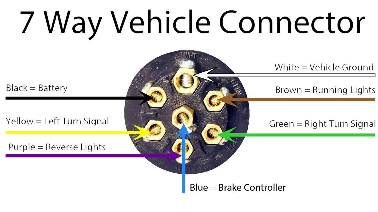
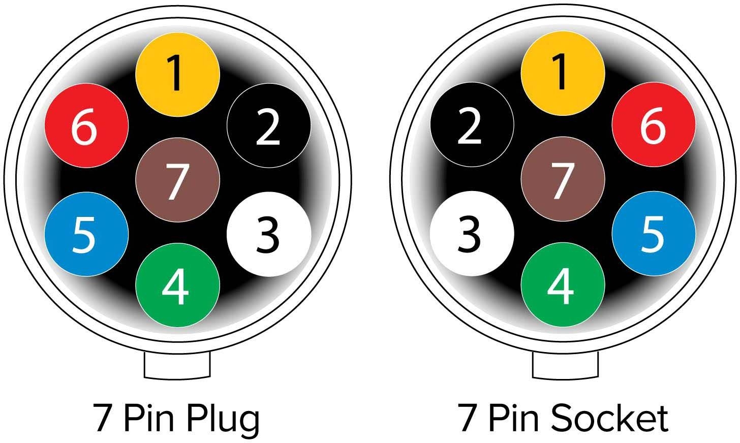
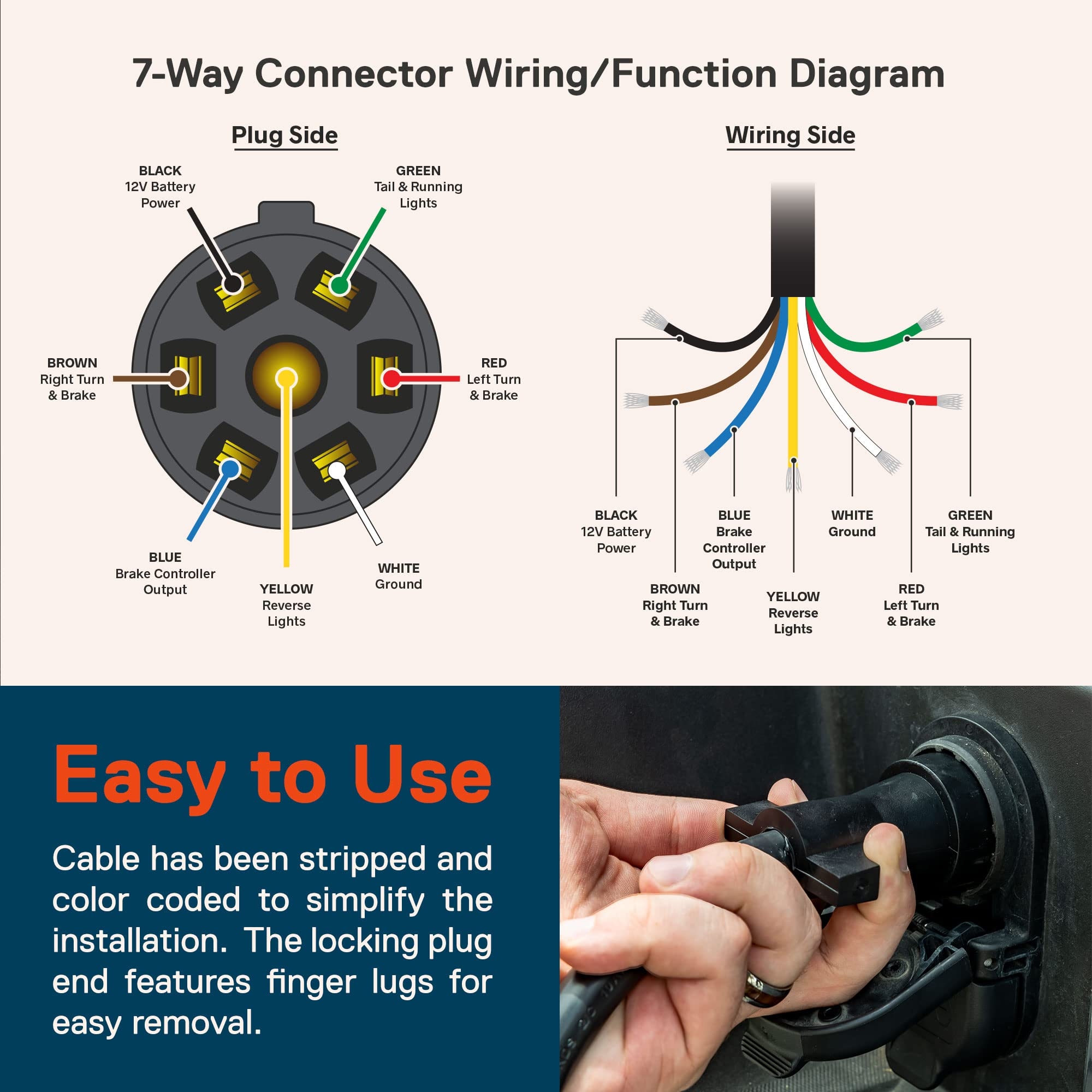
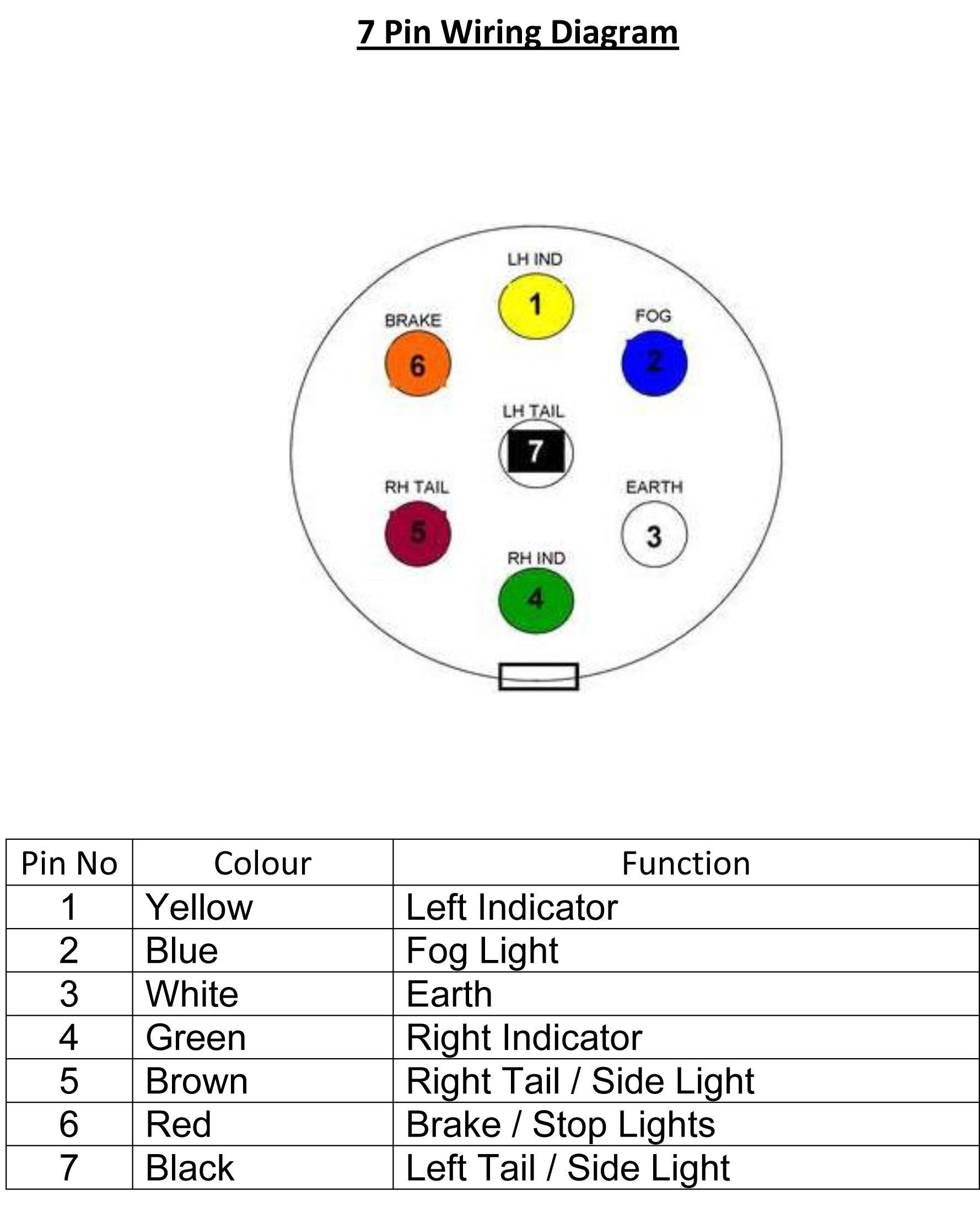
Before we jump into the wiring diagram, let’s first break down the different pins of a standard 7 pin connector. Each pin serves a specific function, from providing power to controlling brake lights. Understanding the purpose of each pin is essential for troubleshooting issues and ensuring proper connections.
Pin 1: Ground
Pin 2: Reverse Lights
Pin 3: Running Lights
Pin 4: Left Turn Signal
Pin 5: Right Turn Signal
Pin 6: Electric Brakes
Pin 7: 12V Auxiliary Power
Deciphering the Wiring Diagram
Now that you’re familiar with the pins, let’s dive into the nitty-gritty of the wiring diagram. This visual representation illustrates how each pin connects to specific components on your trailer. By following the diagram meticulously, you can ensure a seamless electrical connection that complies with safety standards and regulations.
Identify the pins on your 7 pin connector.
Refer to the wiring diagram for your trailer model.
Match the pins on the connector to the corresponding wires on the diagram.
Use a voltage tester to verify connections and troubleshoot any issues.
Tips for Trouble-Free Towing
To make your towing experience hassle-free, here are some expert tips to keep in mind when working with your trailer’s 7 pin connector:
Regularly inspect and clean the connector to prevent corrosion.
Secure all connections to avoid loose wires and potential hazards.
Follow the color-coding on the wiring diagram for accuracy.
Consult a professional if you encounter complex wiring issues.
Final Thoughts
Mastering the art of trailer 7 pin connector wiring is a valuable skill that every trailer owner should possess. By familiarizing yourself with the wiring diagram and following best practices, you can ensure a safe and efficient towing experience. Whether you’re a seasoned pro or a novice in the world of trailers, understanding the intricacies of the 7 pin connector will undoubtedly elevate your towing game!
Related to Trailer 7 Pin Connector Wiring Diagram
- Trailer 4 Pin Wiring Diagram
- Trailer 4 Plug Wiring Diagram
- Trailer 4 Prong Wiring Diagram
- Trailer 4 Way Wiring Diagram
- Trailer 7 Blade Wiring Diagram
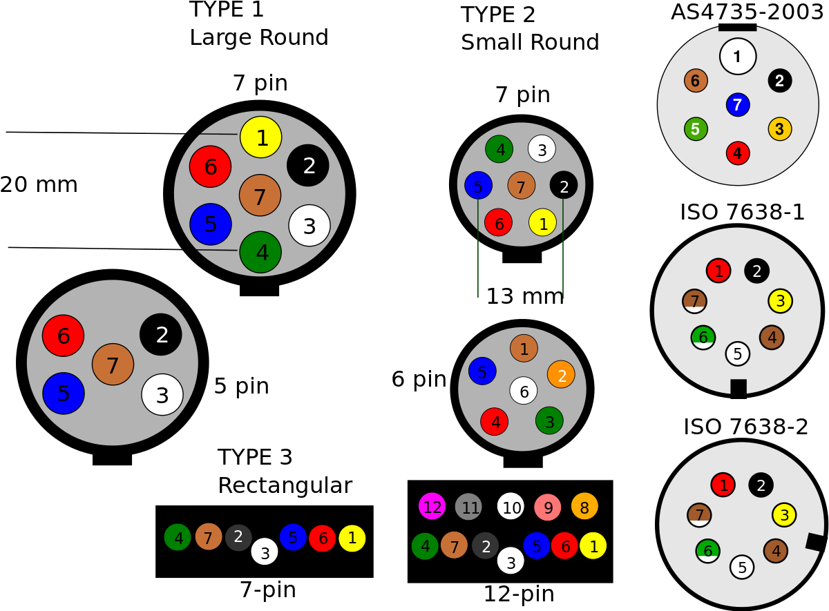
Trailer Connectors In Australia Wikipedia
The image title is Trailer Connectors In Australia Wikipedia, features dimensions of width 1200 px and height 885 px, with a file size of 1200 x 885 px. This image image/png type visual are source from en.wikipedia.org.
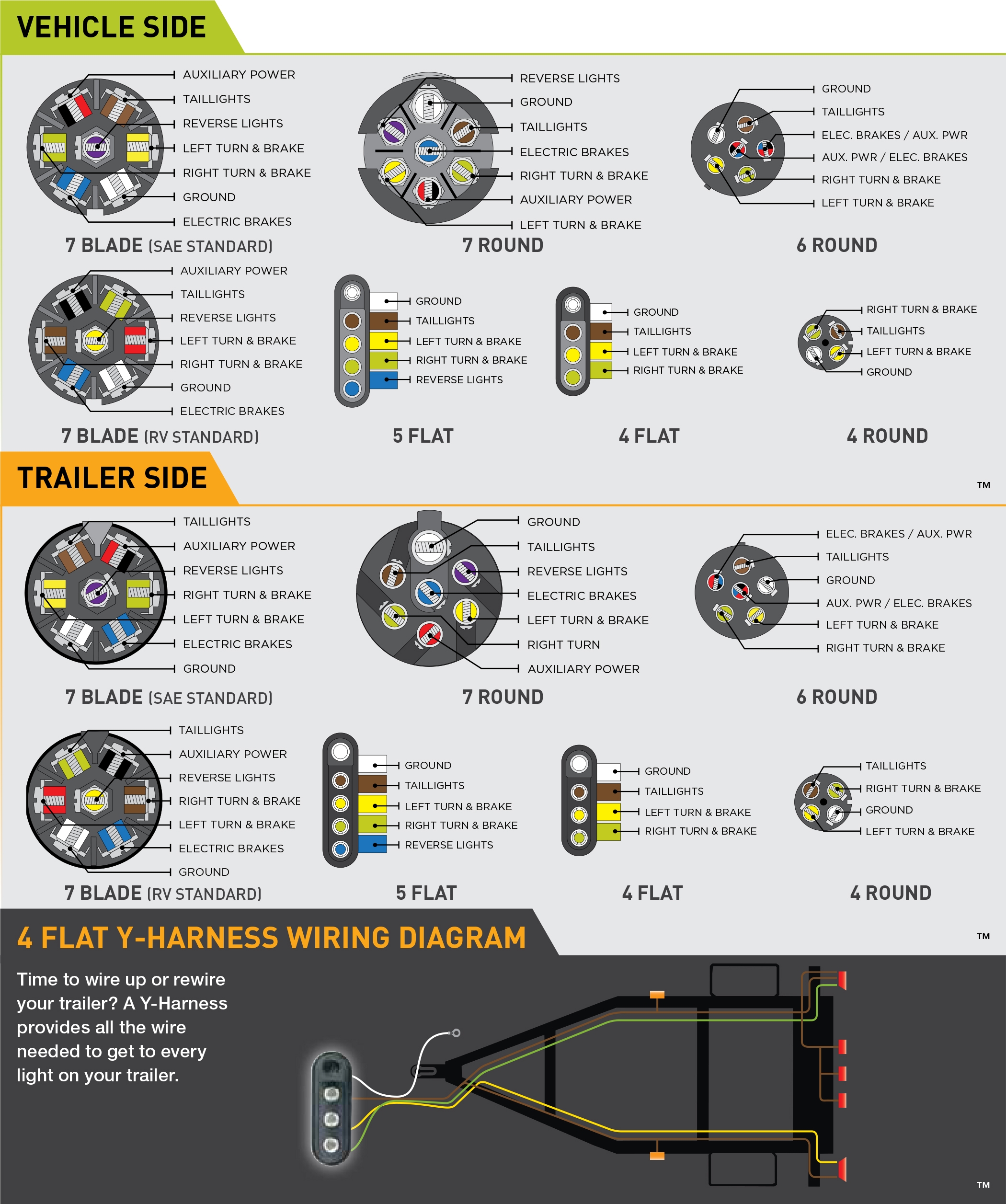
Wiring Guides
The image title is Wiring Guides, features dimensions of width 2100 px and height 2513 px, with a file size of 2100 x 2513 px. This image image/jpeg type visual are source from www.hopkinstowingsolutions.com.
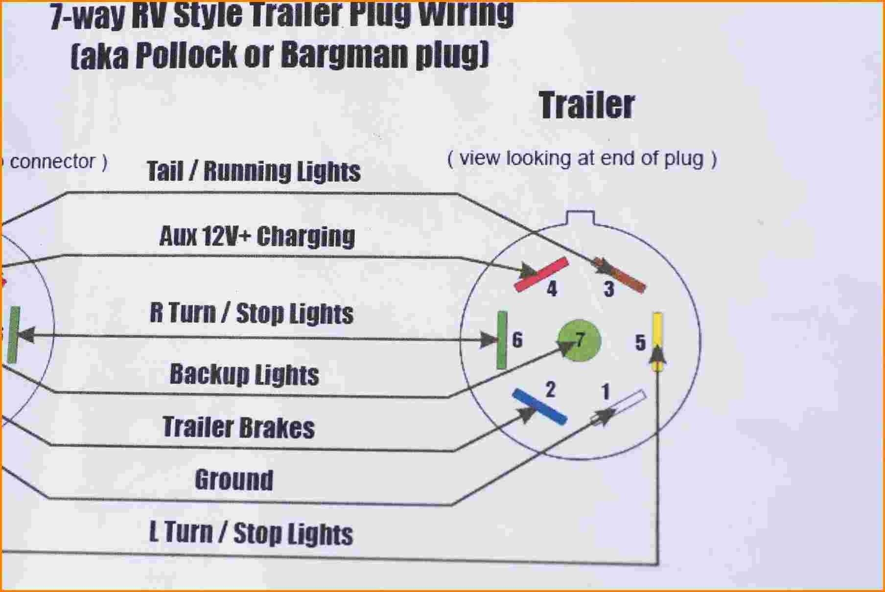
Best Of Wiring Diagram 7 Pin Trailer Plug Toyota Diagrams Digramssample Diagramimages Check Trailer Wiring Diagram Trailer Light Wiring Boat Trailer Lights
The image title is Best Of Wiring Diagram 7 Pin Trailer Plug Toyota Diagrams Digramssample Diagramimages Check Trailer Wiring Diagram Trailer Light Wiring Boat Trailer Lights, features dimensions of width 1808 px and height 1210 px, with a file size of 1808 x 1210. This image image/jpeg type visual are source from www.pinterest.com.
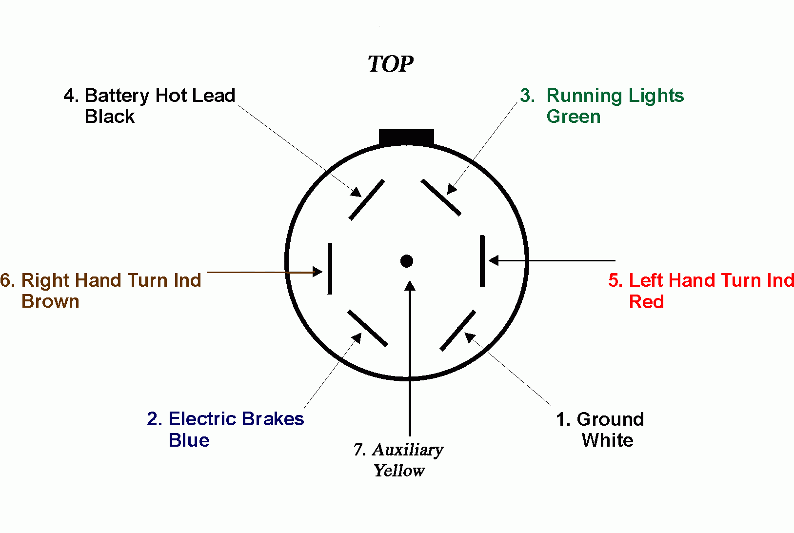
TRAILER WIRING INFORMATION
The image title is TRAILER WIRING INFORMATION, features dimensions of width 1628 px and height 1093 px, with a file size of 1628 x 1093. This image image/gif type visual are source from iegtoclub.com.
Dodge 7 Way Trailer Plug Wiring Diagram Wiring Diagram Strategiccontentmarketing Co Trailer Wiring Diagram Trailer Light Wiring Boat Trailer Lights
The image title is Dodge 7 Way Trailer Plug Wiring Diagram Wiring Diagram Strategiccontentmarketing Co Trailer Wiring Diagram Trailer Light Wiring Boat Trailer Lights, features dimensions of width 1300 px and height 730 px, with a file size of 1300 x 730. This image image/jpeg type visual are source from www.pinterest.com
Narva Trailer Plug Wiring Guide
The image title is Narva Trailer Plug Wiring Guide, features dimensions of width 1456 px and height 872 px, with a file size of 1456 x 872. This image image/jpeg type visual are source from www.narva.com.au.
Amazon True Mods 16ft 7 Pin Trailer Plug Cord Wire Cable 7 Way Trailer Wiring Harness Brake Light Control 10 14AWG 7 Prong Trailer Light Wiring Connector For RV Automotive
The image title is Amazon True Mods 16ft 7 Pin Trailer Plug Cord Wire Cable 7 Way Trailer Wiring Harness Brake Light Control 10 14AWG 7 Prong Trailer Light Wiring Connector For RV Automotive, features dimensions of width 2000 px and height 2000 px, with a file size of 2000 x 2000. This image image/jpeg type visual are source from www.amazon.com.
Best Way To Figure Out 7 Pin Trailer Wiring Wiring Diagram Image Trailer Light Wiring Trailer Wiring Diagram Boat Trailer Lights
The image title is Best Way To Figure Out 7 Pin Trailer Wiring Wiring Diagram Image Trailer Light Wiring Trailer Wiring Diagram Boat Trailer Lights, features dimensions of width 1778 px and height 2218 px, with a file size of 1778 x 2218.
The images on this page, sourced from Google for educational purposes, may be copyrighted. If you own an image and wish its removal or have copyright concerns, please contact us. We aim to promptly address these issues in compliance with our copyright policy and DMCA standards. Your cooperation is appreciated.
Related Keywords to Trailer 7 Pin Connector Wiring Diagram:
semi trailer 7 pin plug wiring diagram,trailer 7 pin connector wiring diagram,trailer 7 pin plug wiring diagram australia,trailer 7 pin socket wiring diagram,trailer side 7 way connector wiring diagram
