Table of Contents
The Comprehensive Guide to Start Stop Wiring Diagram
When it comes to understanding the intricate workings of electrical systems, a Start Stop Wiring Diagram serves as a vital tool for both beginners and seasoned professionals. This diagram provides a clear and concise visual representation of how the start-stop circuit is wired, offering valuable insights into the connections and components involved. Whether you’re troubleshooting an existing system or designing a new one, having a thorough understanding of the start-stop wiring diagram is essential for ensuring smooth operation and preventing potential issues.
The Basics of Start Stop Wiring Diagram
At its core, a start-stop wiring diagram illustrates the electrical connections between the start and stop buttons, control relays, motor starters, and other components in a circuit. By delineating the path of power flow and the interaction between various elements, this diagram simplifies the complex relationships within a control system. Understanding how these components work together is crucial for troubleshooting faults, optimizing performance, and ensuring the safety of the system.
Key Components in a Start Stop Wiring Diagram
Several key components feature prominently in a start-stop wiring diagram, each playing a crucial role in the overall functionality of the system. These components include:
- Start Button: Initiates the circuit and sends power to the motor starter.
- Stop Button: Interrupts the circuit and halts power to the motor starter.
- Control Relay: Controls the flow of power between the start and stop buttons.
- Motor Starter: Engages the motor and provides the necessary power for operation.
Understanding the Wiring Connections
One of the primary benefits of a start-stop wiring diagram is its ability to clearly illustrate the wiring connections between different components. By following the lines and symbols in the diagram, you can easily trace the path of power flow and identify any potential issues or misconnections. This visual representation simplifies the troubleshooting process and helps you pinpoint the source of any electrical faults.
Common Wiring Configurations
There are several common wiring configurations used in start-stop circuits, each with its unique advantages and applications. Some of the most prevalent configurations include:
- Direct On-Line (DOL) Starter: A simple and robust wiring setup that directly connects the motor to the power source.
- Star-Delta Starter: Ideal for reducing motor starting currents and minimizing voltage dips during startup.
- Reversing Starter: Allows the motor to run in both directions by reversing the phase sequence.
Best Practices for Start Stop Wiring
To ensure the efficiency and safety of your start-stop wiring system, it’s essential to adhere to best practices and industry standards. Some key tips to keep in mind include:
- Use color-coded wires for easy identification and troubleshooting.
- Properly insulate all connections to prevent short circuits or electrical hazards.
- Regularly inspect and maintain the wiring system to address any wear or damage promptly.
Conclusion
In conclusion, the Start Stop Wiring Diagram is a valuable resource that provides a comprehensive overview of the electrical connections and components in a start-stop circuit. By understanding the basics of this diagram, you can troubleshoot faults, optimize performance, and ensure the smooth operation of your control system. Remember to follow best practices and industry standards to maintain the efficiency and safety of your wiring setup. With this knowledge in hand, you’ll be well-equipped to tackle any challenges that come your way in the realm of electrical systems.
Related to Start Stop Wiring Diagram
- Square D 100 Amp Panel Wiring Diagram
- Square D 60 Amp Disconnect Wiring Diagram
- Square D Homeline 100 Amp Panel Wiring Diagram
- Square D Homeline 200 Amp Panel Wiring Diagram
- Start Run Capacitor Wiring Diagram
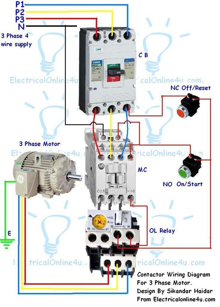
DIAGRAM 3 Phase Emergency Stop Wiring Diagram FULL Circuit Diagram Electrical Circuit Diagram Electrical Wiring Diagram
The image title is DIAGRAM 3 Phase Emergency Stop Wiring Diagram FULL Circuit Diagram Electrical Circuit Diagram Electrical Wiring Diagram, features dimensions of width 736 px and height 1026 px, with a file size of 736 x 1026 px. This image image/jpeg type visual are source from www.pinterest.com.
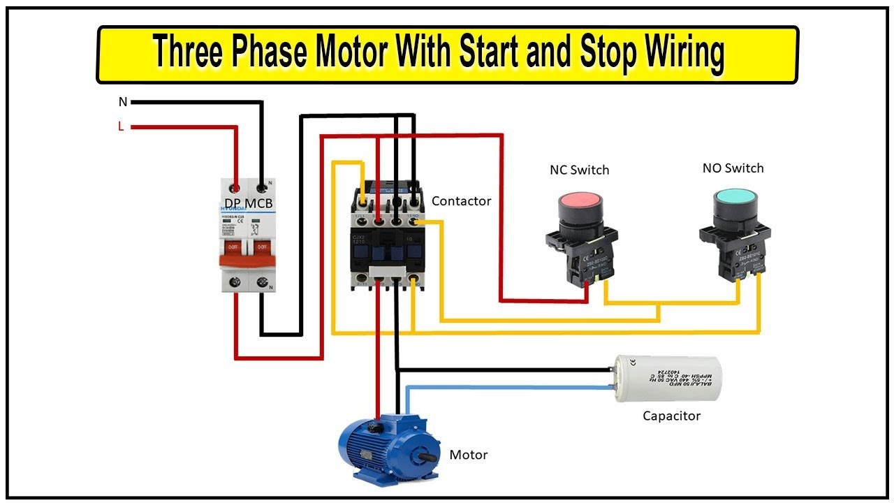
How To Make Three Phase Motor With Start And Stop Wiring Diagram 3 Phase Motor Switch Wiring YouTube
The image title is How To Make Three Phase Motor With Start And Stop Wiring Diagram 3 Phase Motor Switch Wiring YouTube, features dimensions of width 1280 px and height 720 px, with a file size of 1280 x 720 px. This image image/jpeg type visual are source from www.youtube.com.
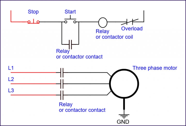
Start Stop Circuit
The image title is Start Stop Circuit, features dimensions of width 768 px and height 523 px, with a file size of 768 x 523. This image image/jpeg type visual are source from www.nextpcb.com.
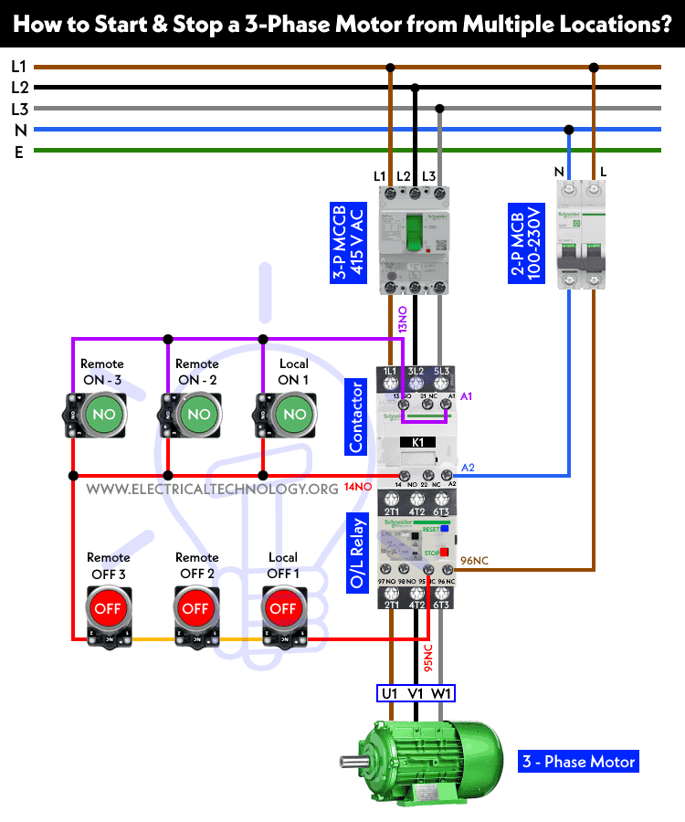
How To Start Stop A 3 Phase Motor From Multiple Locations
The image title is How To Start Stop A 3 Phase Motor From Multiple Locations, features dimensions of width 750 px and height 900 px, with a file size of 750 x 900. This image image/png type visual are source from www.electricaltechnology.org.
3 Phase Motor Control Wiring Diagram Connection To Emergency Stop Switch YouTube
The image title is 3 Phase Motor Control Wiring Diagram Connection To Emergency Stop Switch YouTube, features dimensions of width 1280 px and height 720 px, with a file size of 1280 x 720. This image image/jpeg type visual are source from m.youtube.com
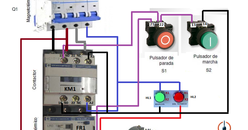
Control Three Phase Motor Starter With Start Stop Buttons Basic Electrical Wiring Electrical Engineering Starter
The image title is Control Three Phase Motor Starter With Start Stop Buttons Basic Electrical Wiring Electrical Engineering Starter, features dimensions of width 797 px and height 418 px, with a file size of 797 x 418. This image image/png type visual are source from www.pinterest.com.
The Essential Guide To Start Stop Diagram RAYPCB
The image title is The Essential Guide To Start Stop Diagram RAYPCB, features dimensions of width 1600 px and height 666 px, with a file size of 1600 x 666. This image image/jpeg type visual are source from www.raypcb.com.
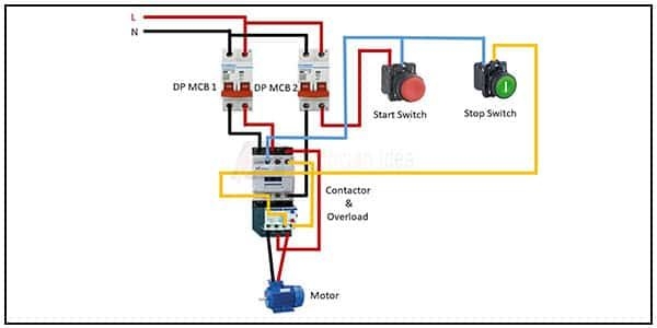
Start And Stop Of A Single Phase Motor Wiring Start Stop Push Button Wiring Diagram Single Phase Circuit Diagram Wire Single
The image title is Start And Stop Of A Single Phase Motor Wiring Start Stop Push Button Wiring Diagram Single Phase Circuit Diagram Wire Single, features dimensions of width 600 px and height 300 px, with a file size of 600 x 300.
The images on this page, sourced from Google for educational purposes, may be copyrighted. If you own an image and wish its removal or have copyright concerns, please contact us. We aim to promptly address these issues in compliance with our copyright policy and DMCA standards. Your cooperation is appreciated.
Related Keywords to Start Stop Wiring Diagram:
start stop connection diagram,start stop wiring diagram,start stop wiring diagram motor,start stop wiring schematic,stop start wiring diagram single phase
