Table of Contents
Exploring Single Phase Contactor Wiring Diagram
The Value of Single Phase Contactor Wiring Diagram
Single phase contactor wiring diagrams are essential tools for anyone working with electrical systems. Whether you are a professional electrician, a DIY enthusiast, or simply interested in understanding how electrical circuits work, these diagrams provide a detailed visual representation of how to wire a single phase contactor accurately. By following the wiring diagram carefully, you can ensure the safety and efficiency of your electrical connections, preventing potential hazards and ensuring that your systems function correctly.
Understanding the Basics
What is a Single Phase Contactor?
Before delving into the wiring diagram, it’s crucial to understand the role of a single phase contactor in electrical systems. A contactor is an electrical device used to control the flow of electricity to a load by opening and closing contacts. In single phase systems, a contactor is typically used to switch power to motors, pumps, heaters, or other devices that require high current levels. By using a contactor, you can safely control the operation of these devices without directly handling the high voltage circuits.
Components of a Single Phase Contactor
A single phase contactor consists of several key components, including the main contacts, auxiliary contacts, coil, and housing. The main contacts are responsible for carrying the load current, while the auxiliary contacts are used for control purposes. The coil generates a magnetic field when energized, causing the contacts to close and complete the circuit. The housing provides protection and insulation for the internal components, ensuring safe operation.
Exploring the Wiring Diagram
Benefits of Using a Wiring Diagram
A wiring diagram for a single phase contactor serves as a roadmap for connecting the various components correctly. By following the diagram, you can avoid errors that may lead to equipment damage or electrical hazards. Additionally, wiring diagrams make it easier to troubleshoot issues and make modifications to the circuit in the future. With a clear understanding of the wiring layout, you can confidently work on electrical installations with precision and efficiency.
Step-by-Step Guide to Wiring a Single Phase Contactor
Identify the terminals on the contactor for power supply, load, and control connections.
Refer to the wiring diagram provided by the manufacturer to determine the correct wiring configuration.
Connect the power supply wires to the designated terminals on the contactor, ensuring proper polarity.
Wire the load circuit to the main contacts of the contactor, following the diagram’s instructions.
Complete the control circuit by connecting the control wires to the auxiliary contacts as indicated.
Double-check all connections and ensure that they are secure before energizing the circuit.
Conclusion
In conclusion, single phase contactor wiring diagrams are invaluable resources for anyone working with electrical systems. By understanding the basics of a contactor and following a detailed wiring diagram, you can ensure the proper installation and operation of your electrical circuits. Whether you are installing a new contactor or troubleshooting an existing system, having a clear and accurate wiring diagram at your disposal will streamline the process and enhance the safety of your electrical work.
Related to Single Phase Contactor Wiring Diagram
- Single Phase 220 Volt Air Compressor Wiring Diagram
- Single Phase 3 Speed Fan Motor Wiring Diagram
- Single Phase 3 Wire Submersible Pump Wiring Diagram
- Single Phase 480 To 120/240 Transformer Wiring Diagram
- Single Phase Air Compressor Wiring Diagram
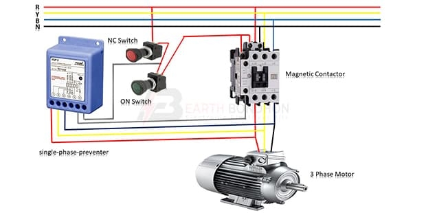
Single Phase Preventer Contactor Phase Failure Relay Electrician Idea
The image title is Single Phase Preventer Contactor Phase Failure Relay Electrician Idea, features dimensions of width 620 px and height 310 px, with a file size of 620 x 310 px. This image image/jpeg type visual are source from www.electricianidea.com.
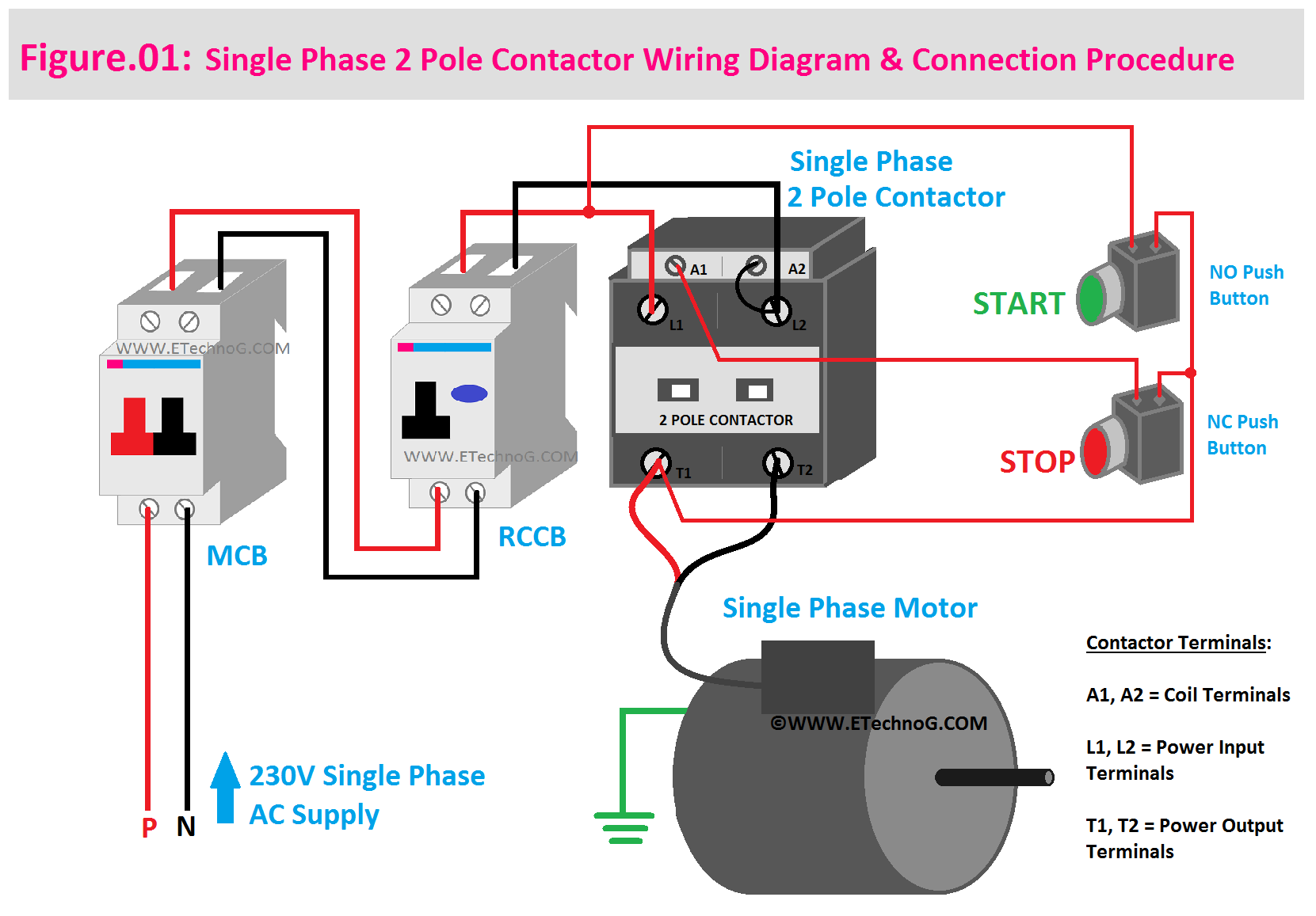
Single Phase 2 Pole Contactor Wiring Diagram Electrical Diagram Electrical Circuit Diagram Pole
The image title is Single Phase 2 Pole Contactor Wiring Diagram Electrical Diagram Electrical Circuit Diagram Pole, features dimensions of width 1661 px and height 1157 px, with a file size of 1661 x 1157 px. This image image/png type visual are source from www.pinterest.com.
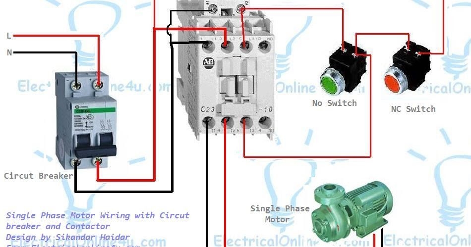
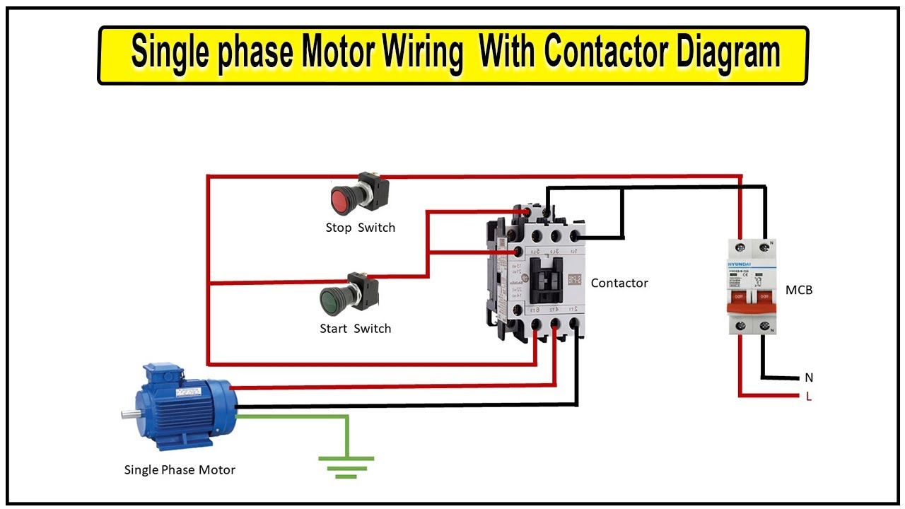
Single Phase Motor Wiring With Contactor Diagram Circuit Diagram Electrical Circuit Diagram Electrical Wiring Diagram
The image title is Single Phase Motor Wiring With Contactor Diagram Circuit Diagram Electrical Circuit Diagram Electrical Wiring Diagram, features dimensions of width 950 px and height 499 px, with a file size of 950 x 499. This image image/jpeg type visual are source from ru.pinterest.com.
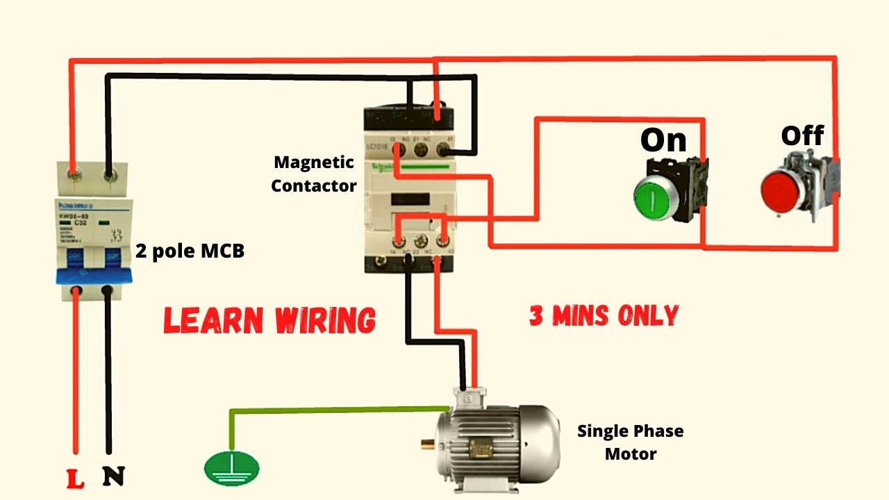
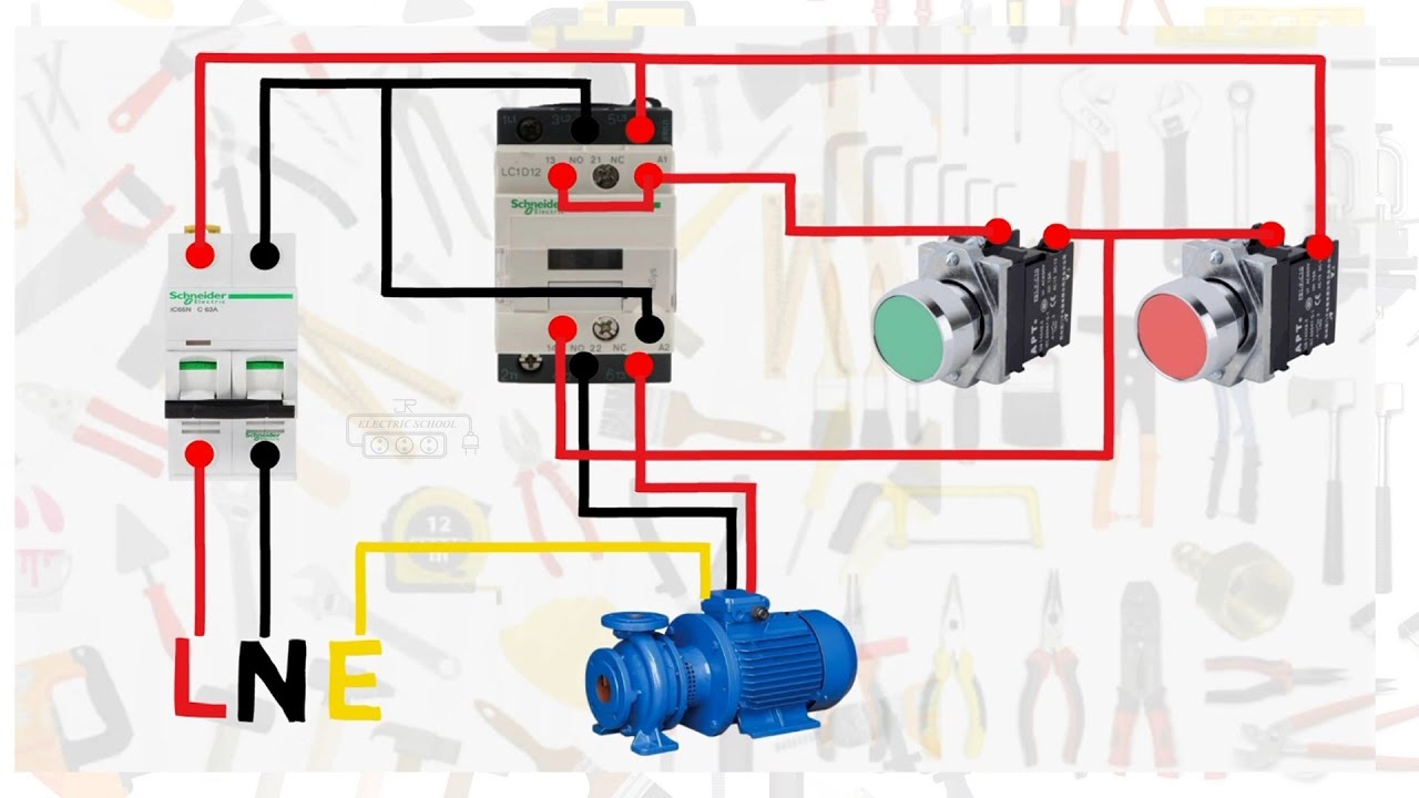
Single Phase Motor Connection With Magnetic Contactor Wiring Diagram YouTube
The image title is Single Phase Motor Connection With Magnetic Contactor Wiring Diagram YouTube, features dimensions of width 1280 px and height 720 px, with a file size of 1280 x 720. This image image/jpeg type visual are source from www.youtube.com.
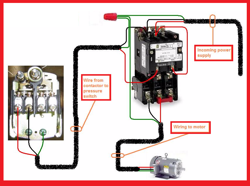
Electrical Wiring House Wiring Electricity
The image title is Electrical Wiring House Wiring Electricity, features dimensions of width 848 px and height 632 px, with a file size of 848 x 632. This image image/png type visual are source from www.pinterest.com
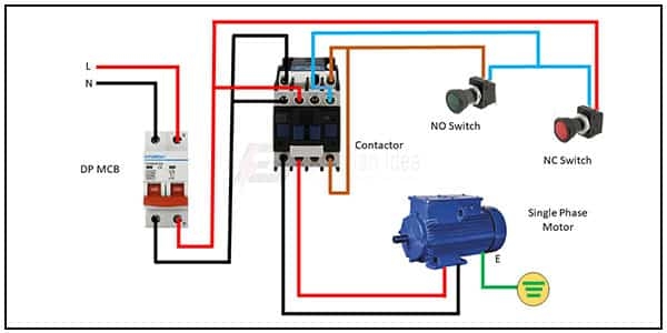
Single Phase Motor Connection Electrician Idea
The image title is Single Phase Motor Connection Electrician Idea, features dimensions of width 600 px and height 300 px, with a file size of 600 x 300. This image image/jpeg type visual are source from www.electricianidea.com.
Single Phase Motor Connection With Magnetic Contactor Wiring Diagram YouTube
The image title is Single Phase Motor Connection With Magnetic Contactor Wiring Diagram YouTube, features dimensions of width 1280 px and height 720 px, with a file size of 1280 x 720. This image image/jpeg type visual are source from www.youtube.com.
How To Make Single Phase Motor Wiring With Contactor Diagram Motor YouTube
The image title is How To Make Single Phase Motor Wiring With Contactor Diagram Motor YouTube, features dimensions of width 1280 px and height 720 px, with a file size of 1280 x 720.
The images on this page, sourced from Google for educational purposes, may be copyrighted. If you own an image and wish its removal or have copyright concerns, please contact us. We aim to promptly address these issues in compliance with our copyright policy and DMCA standards. Your cooperation is appreciated.
Related Keywords to Single Phase Contactor Wiring Diagram:
single phase contactor wiring diagram,single phase contactor wiring diagram a1 a2,single phase contactor wiring diagram pdf,single phase contactor wiring diagram start stop pdf,single phase contactor wiring diagram with timer
