Table of Contents
Rpm Tachometer Wiring Diagram
The Value of Rpm Tachometer Wiring Diagram
When it comes to understanding the inner workings of your vehicle, having a clear and concise Rpm Tachometer Wiring Diagram can be invaluable. This diagram serves as a roadmap for connecting the various components of your tachometer, ensuring that it functions correctly and provides accurate readings. By following a well-crafted wiring diagram, you can troubleshoot issues, make modifications, or install a new tachometer with ease. Let’s delve into the world of Rpm Tachometer Wiring Diagrams and explore the wealth of information they offer.
The Basics of Rpm Tachometer Wiring Diagram
At its core, an Rpm Tachometer Wiring Diagram outlines the connections between the tachometer and other vital components of your vehicle, such as the ignition system and engine control module. By visually representing these connections, the diagram simplifies the installation process and aids in diagnosing any potential issues that may arise. Whether you’re a seasoned mechanic or a DIY enthusiast, having a reliable wiring diagram at your disposal can make all the difference in achieving optimal performance from your tachometer.
Benefits of Using a Rpm Tachometer Wiring Diagram
Ensures proper connection of components
Aids in troubleshooting electrical issues
Facilitates modifications or upgrades
Enhances overall performance and accuracy of the tachometer
Key Components of Rpm Tachometer Wiring Diagram
A typical Rpm Tachometer Wiring Diagram includes detailed illustrations of the tachometer itself, as well as the connections to the power source, ground, and signal input. Additionally, it may highlight specific wire colors, terminal locations, and recommended gauges for optimal performance. Understanding these key components is crucial for successfully interpreting and implementing the wiring diagram in your vehicle.
Tips for Reading and Interpreting Rpm Tachometer Wiring Diagram
Familiarize yourself with the symbols and abbreviations used in the diagram
Double-check wire colors and terminal connections for accuracy
Refer to the manufacturer’s instructions for any specific guidelines
Seek professional assistance if you encounter any difficulties
Conclusion
In conclusion, a well-crafted Rpm Tachometer Wiring Diagram is an essential tool for anyone looking to install, troubleshoot, or upgrade their tachometer. By providing a visual representation of the connections and components involved, the diagram streamlines the process and ensures optimal performance of the tachometer. Whether you’re a novice or an expert in automotive electronics, having a reliable wiring diagram can save you time, effort, and frustration. Embrace the power of Rpm Tachometer Wiring Diagrams and unlock the potential of your vehicle’s performance!
Related to Rpm Tachometer Wiring Diagram
- Rocker Switch Wiring Diagram
- Rockford Fosgate Amp Wiring Diagram
- Round 7 Pin Wiring Diagram
- Rp5 Gm11 Wiring Diagram
- Rp5 Gm31 Wiring Diagram
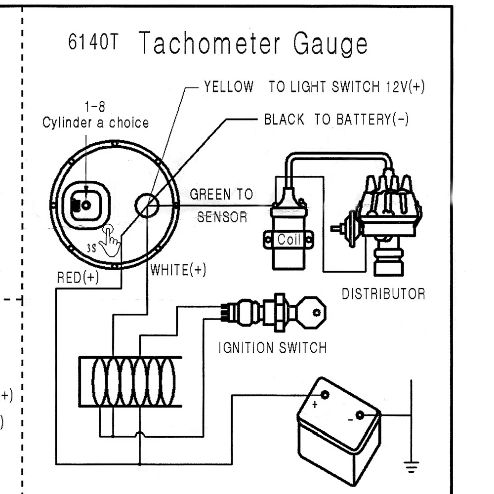
0 8000 RPM Tachometer Blue Light Pointer 52mm Tacho Gauge Fit 1 8 Cylinder Enginee For Auto Universal Gasoline Car 12V AliExpress
The image title is 0 8000 RPM Tachometer Blue Light Pointer 52mm Tacho Gauge Fit 1 8 Cylinder Enginee For Auto Universal Gasoline Car 12V AliExpress, features dimensions of width 1000 px and height 1000 px, with a file size of 1000 x 1000 px. This image image/jpeg type visual are source from s.click.aliexpress.com.
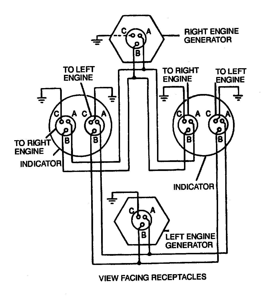
Figure 4 17 Dual Synchronous Rotor Tachometer Wiring Diagram
The image title is Figure 4 17 Dual Synchronous Rotor Tachometer Wiring Diagram, features dimensions of width 1136 px and height 1267 px, with a file size of 1136 x 1267 px. This image image/jpeg type visual are source from aviationmiscmanuals.tpub.com.
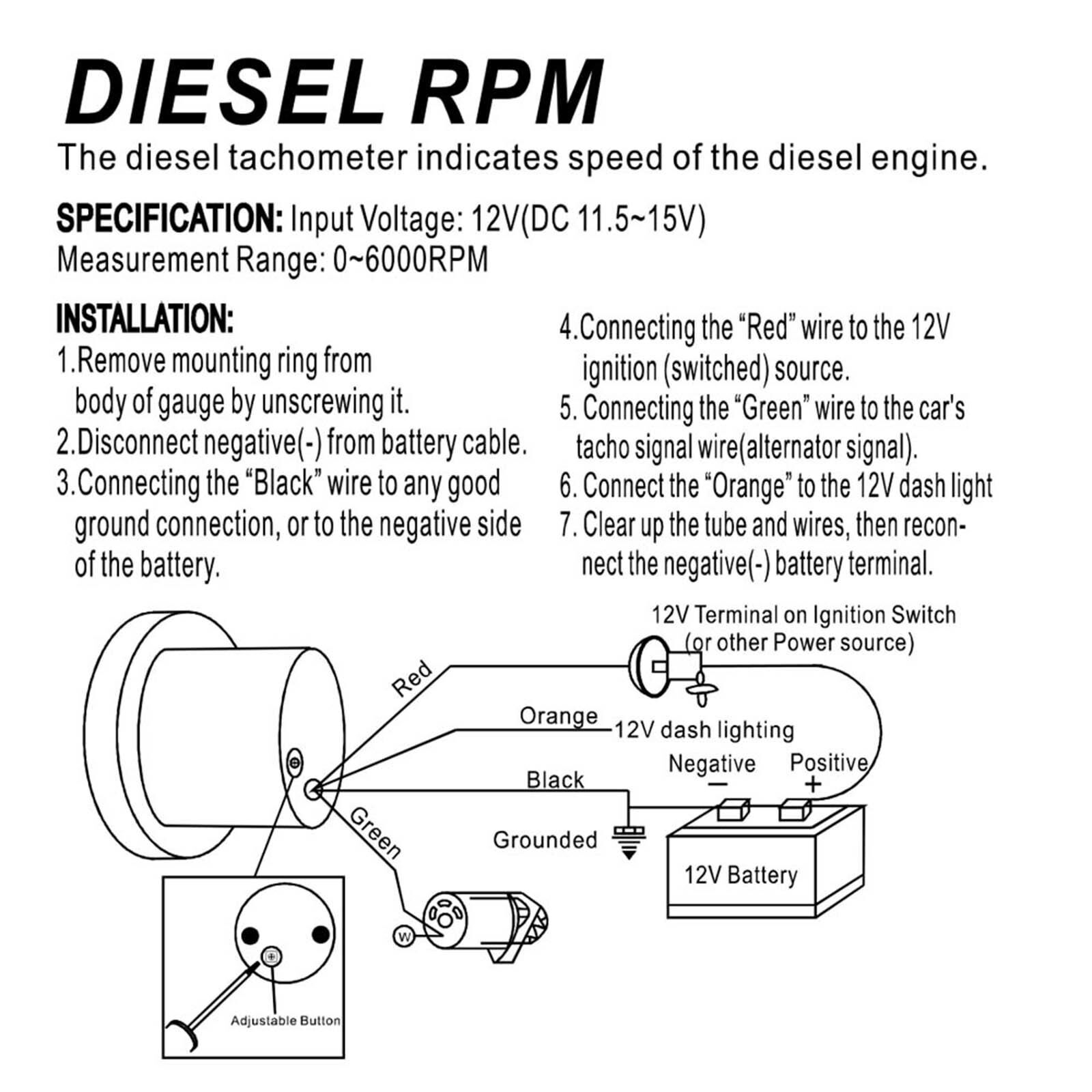
52mm 0 6000 RPM On Dash White Electrical Tachometer Gauge For Diesel Motor EBay
The image title is 52mm 0 6000 RPM On Dash White Electrical Tachometer Gauge For Diesel Motor EBay, features dimensions of width 1600 px and height 1600 px, with a file size of 1600 x 1600. This image image/jpeg type visual are source from www.ebay.com.
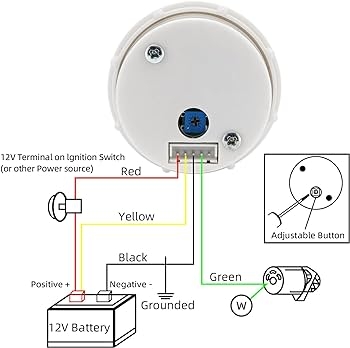
Amazon Faymizsa Diesel Tachometer 6000 RPM Electrical Tachometer Gauge 52mm 2 1 16 For Diesel Motor Alternator Automotive
The image title is Amazon Faymizsa Diesel Tachometer 6000 RPM Electrical Tachometer Gauge 52mm 2 1 16 For Diesel Motor Alternator Automotive, features dimensions of width 350 px and height 348 px, with a file size of 350 x 348. This image image/jpeg type visual are source from www.amazon.com.
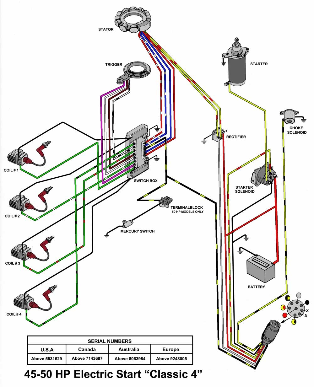
Hall Effect How Does A Tachometer Measure RPM Of A Motor Off Of One Wire From The Unrectified Signal Of The Stator Electrical Engineering Stack Exchange
The image title is Hall Effect How Does A Tachometer Measure RPM Of A Motor Off Of One Wire From The Unrectified Signal Of The Stator Electrical Engineering Stack Exchange, features dimensions of width 1000 px and height 1233 px, with a file size of 1000 x 1233. This image image/jpeg type visual are source from electronics.stackexchange.com
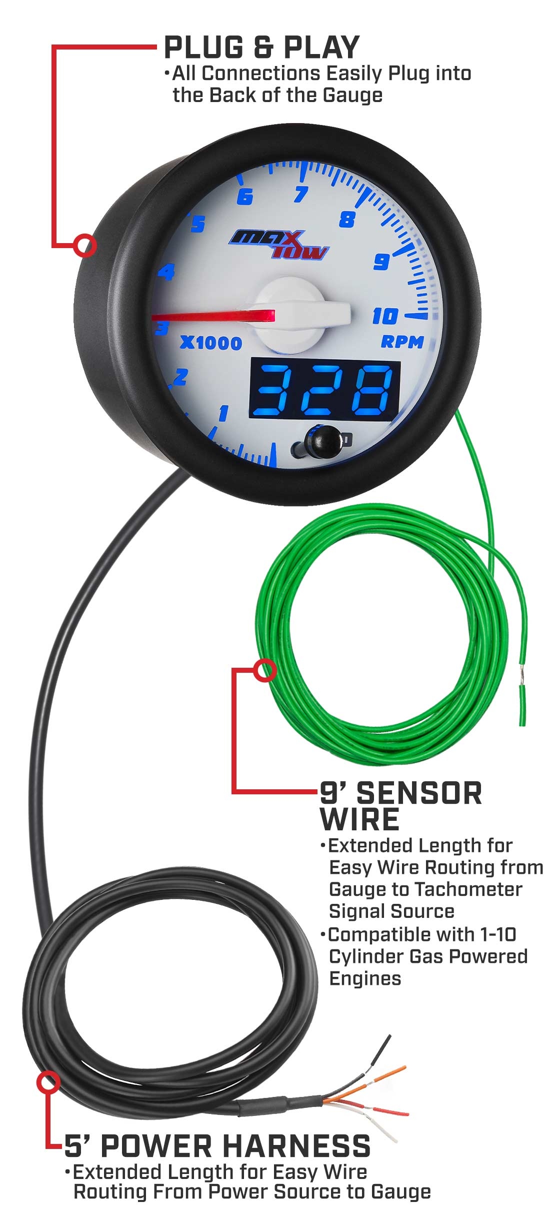
GlowShift MaxTow White Blue Double Vision Truck Tachometer RPM Gauge
The image title is GlowShift MaxTow White Blue Double Vision Truck Tachometer RPM Gauge, features dimensions of width 1110 px and height 2433 px, with a file size of 1110 x 2433. This image image/jpeg type visual are source from www.glowshiftdirect.com.
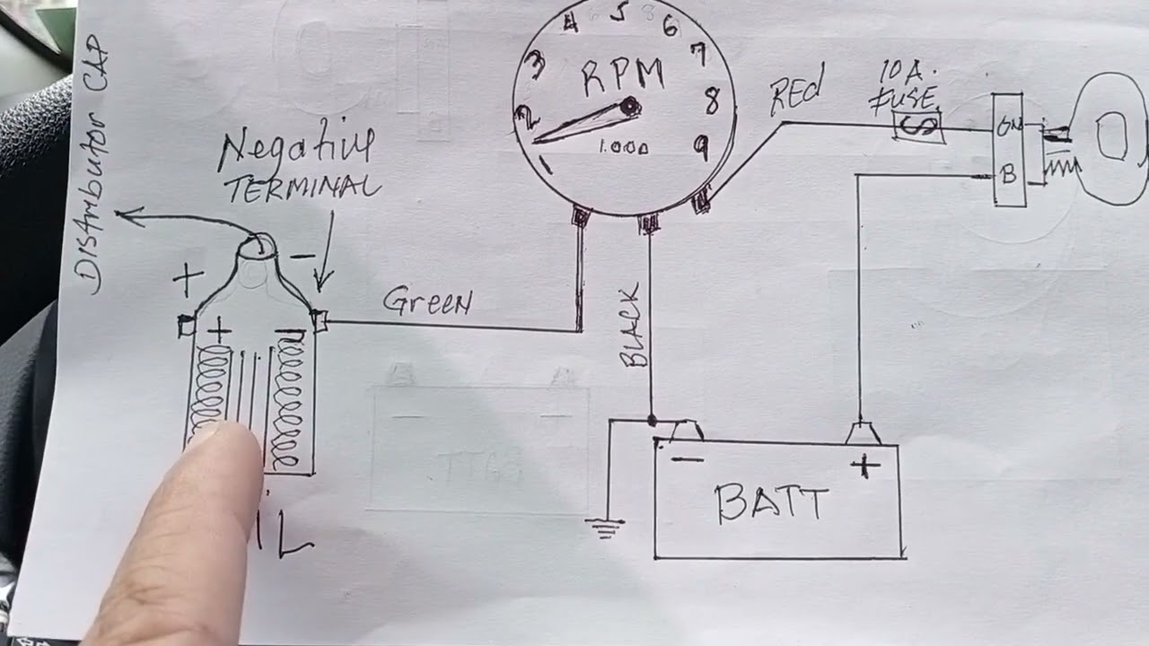
RPM GAUGE WIRING TUTORIALS YouTube
The image title is RPM GAUGE WIRING TUTORIALS YouTube, features dimensions of width 1280 px and height 720 px, with a file size of 1280 x 720. This image image/jpeg type visual are source from www.youtube.com.
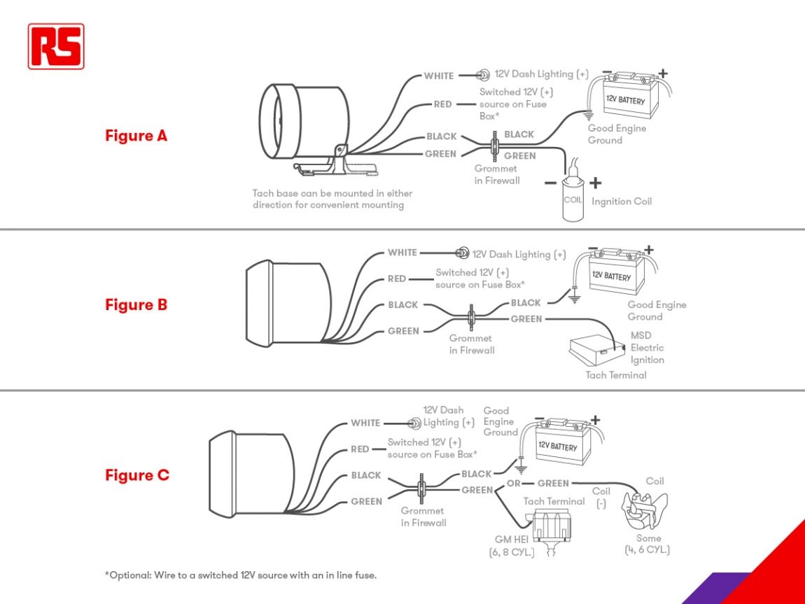
Tachometers A Complete Guide
The image title is Tachometers A Complete Guide, features dimensions of width 1150 px and height 863 px, with a file size of 1150 x 863.
The images on this page, sourced from Google for educational purposes, may be copyrighted. If you own an image and wish its removal or have copyright concerns, please contact us. We aim to promptly address these issues in compliance with our copyright policy and DMCA standards. Your cooperation is appreciated.
Related Keywords to Rpm Tachometer Wiring Diagram:
rpm meter circuit diagram,rpm meter connection diagram,rpm meter wiring diagram,rpm meter wiring diagram motorcycle,rpm tachometer wiring diagram
