Table of Contents
The Ultimate Guide to Receptacle Wiring Diagrams
The Value of Receptacle Wiring Diagrams
When it comes to electrical work, having a clear and detailed understanding of receptacle wiring diagrams is essential. These diagrams provide a visual representation of how electrical outlets are wired in a circuit, allowing electricians and DIY enthusiasts to troubleshoot issues, make repairs, or install new outlets with precision and safety. By following a receptacle wiring diagram, you can ensure that your electrical setup is efficient, code-compliant, and most importantly, safe for everyday use.
Understanding Receptacle Wiring Diagrams
Components of a Wiring Diagram
A typical receptacle wiring diagram consists of various components, including the outlet itself, the wiring connections, and any additional devices such as switches or ground fault circuit interrupters (GFCIs). Each component is represented by specific symbols that indicate its function and connection points within the circuit.
Types of Wiring Diagrams
There are different types of receptacle wiring diagrams, depending on the complexity of the circuit and the specific requirements of the installation. Some common types include single outlet diagrams, multiple outlet diagrams, and diagrams for specialized outlets like GFCIs or tamper-resistant receptacles. Each type serves a unique purpose and provides valuable insights into the wiring configuration.
Benefits of Using Receptacle Wiring Diagrams
Accurate Installation
One of the primary benefits of using receptacle wiring diagrams is the ability to ensure accurate installation of electrical outlets. By following the diagram carefully, you can identify the correct wiring connections, wire sizes, and placement of devices, resulting in a properly functioning outlet that meets safety standards.
Troubleshooting Assistance
In cases where an outlet is malfunctioning or not working as expected, a wiring diagram can be a valuable troubleshooting tool. By comparing the actual wiring configuration to the diagram, you can pinpoint any issues such as loose connections, faulty wiring, or incorrect installations, making it easier to diagnose and fix the problem.
Steps to Read a Receptacle Wiring Diagram
Start by identifying the symbols used in the diagram, such as outlets, wires, switches, and GFCIs.
Trace the wiring connections from the power source to the outlet, following the flow of electricity through the circuit.
Verify the color-coding of the wires and ensure they are connected correctly as per the diagram.
Check for any additional devices or components in the circuit and understand their function within the wiring configuration.
Conclusion
In conclusion, receptacle wiring diagrams are invaluable tools for anyone working with electrical outlets. By understanding the components, types, and benefits of these diagrams, you can improve your electrical knowledge and skills, ensuring safe and efficient installations every time. Whether you are a professional electrician or a DIY enthusiast, mastering the art of reading and interpreting receptacle wiring diagrams is a crucial step towards becoming a proficient and knowledgeable electrician.
Related to Receptacle Wiring Diagram
- Rca Cable Wiring Diagram
- Rca Wiring Diagram
- Reading Schematics Wiring Diagrams
- Reading Wiring Diagrams
- Rear View Camera Wiring Diagram
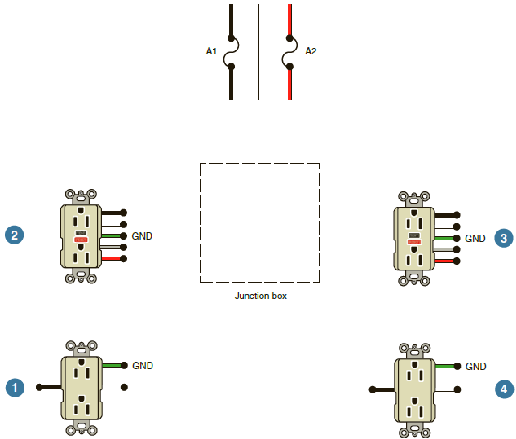
Complete The Wiring Diagram Connecting Feed Through GFCI 2 To Also Protect Receptacle 1 Both To Be Supplied By Circuit A1 Connect Feed Through GFCI 3 To Also Protect Receptacle 4 Both To Be
The image title is Complete The Wiring Diagram Connecting Feed Through GFCI 2 To Also Protect Receptacle 1 Both To Be Supplied By Circuit A1 Connect Feed Through GFCI 3 To Also Protect Receptacle 4 Both To Be, features dimensions of width 1791 px and height 1523 px, with a file size of 1791 x 1523 px. This image image/png type visual are source from www.bartleby.com.
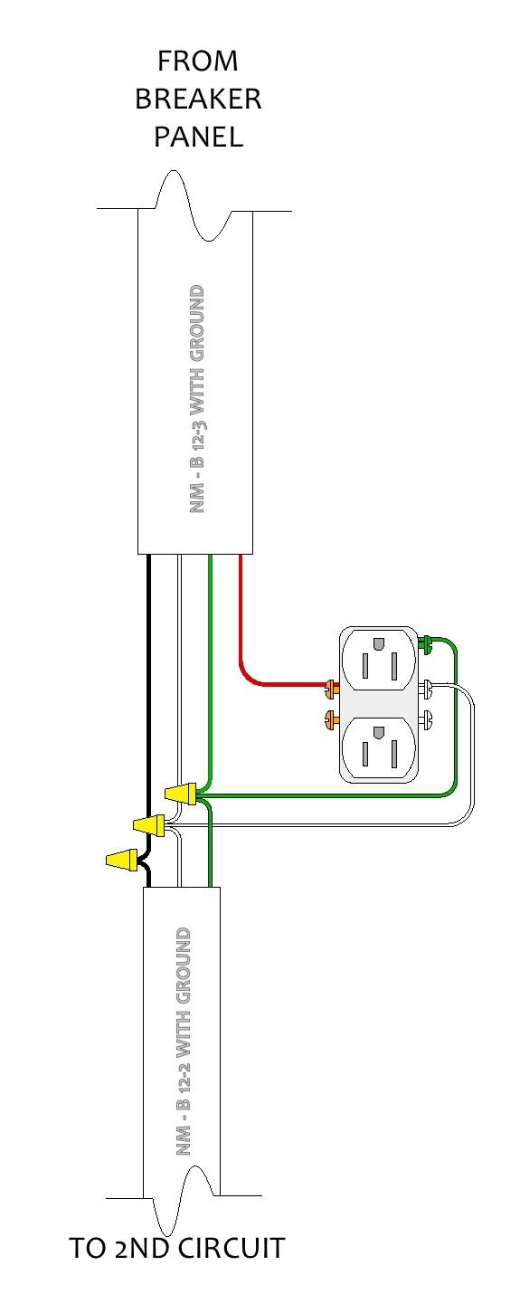
A Kitchen Remodel 5 Kitchen Electrical Designandtechtheatre
The image title is A Kitchen Remodel 5 Kitchen Electrical Designandtechtheatre, features dimensions of width 575 px and height 1430 px, with a file size of 575 x 1430 px. This image image/jpeg type visual are source from designandtechtheatre.wordpress.com.
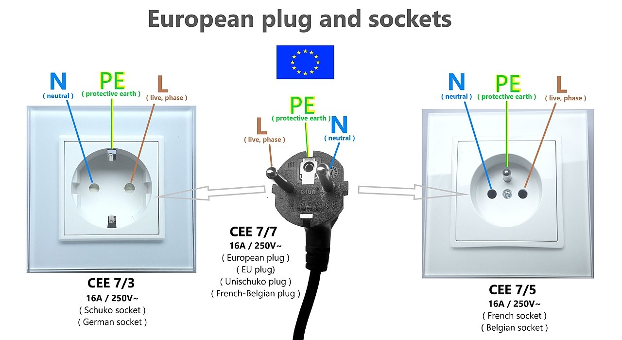
File European Plug And Sockets UE Standard EU Plug And Socket Wiring Diagram Schuko French Socket Cee 7 7 Jpg Wikimedia Commons
The image title is File European Plug And Sockets UE Standard EU Plug And Socket Wiring Diagram Schuko French Socket Cee 7 7 Jpg Wikimedia Commons, features dimensions of width 1280 px and height 699 px, with a file size of 1280 x 699. This image image/jpeg type visual are source from commons.wikimedia.org.
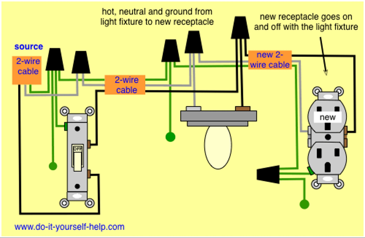
Is There A Way To Do 2D Wiring Diagrams In SketchUp Pro Pro SketchUp Community
The image title is Is There A Way To Do 2D Wiring Diagrams In SketchUp Pro Pro SketchUp Community, features dimensions of width 1500 px and height 982 px, with a file size of 1500 x 982. This image image/jpeg type visual are source from forums.sketchup.com.
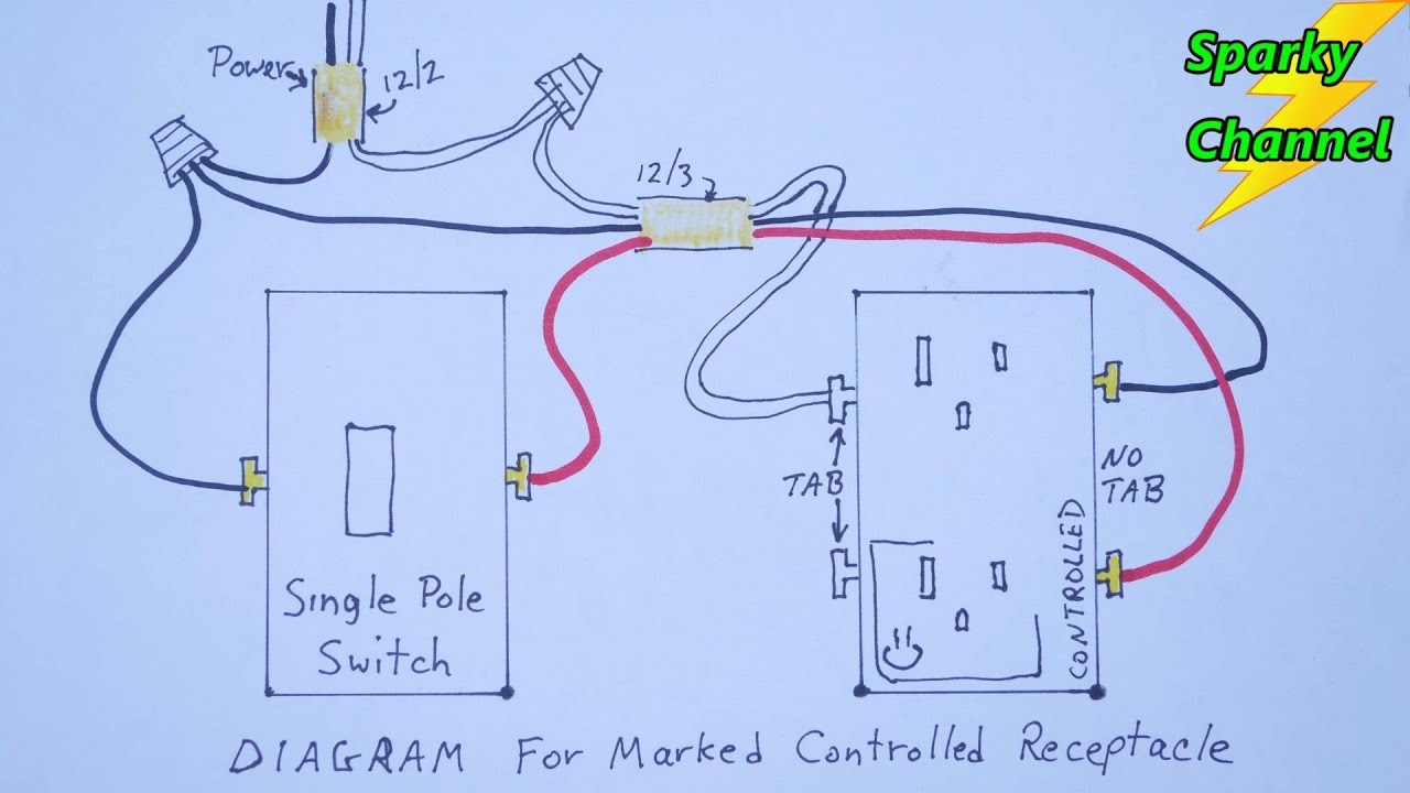
Diagram For Marked Controlled Receptacles With Discussion YouTube
The image title is Diagram For Marked Controlled Receptacles With Discussion YouTube, features dimensions of width 1280 px and height 720 px, with a file size of 1280 x 720. This image image/jpeg type visual are source from www.youtube.com
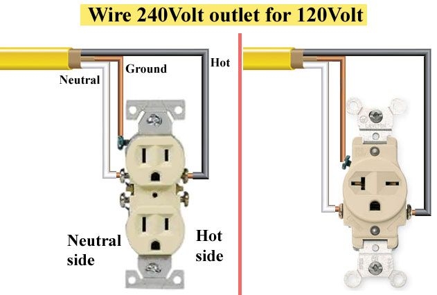
Electrical Plug Wiring Home Electrical Wiring Outlet Wiring
The image title is Electrical Plug Wiring Home Electrical Wiring Outlet Wiring, features dimensions of width 631 px and height 426 px, with a file size of 631 x 426. This image image/jpeg type visual are source from www.pinterest.com.
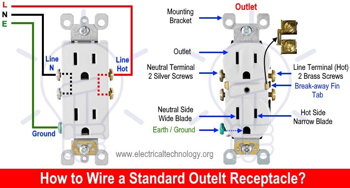
How To Wire An Outlet Receptacle Socket Outlet Wiring Diagrams Outlet Wiring Home Electrical Wiring Electrical Wiring Diagram
The image title is How To Wire An Outlet Receptacle Socket Outlet Wiring Diagrams Outlet Wiring Home Electrical Wiring Electrical Wiring Diagram, features dimensions of width 710 px and height 382 px, with a file size of 710 x 382. This image image/jpeg type visual are source from in.pinterest.com.
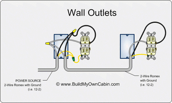
Electrical Wiring Diagram Configuration For 8 Outlets With 1 GFCI Home Improvement Stack Exchange
The image title is Electrical Wiring Diagram Configuration For 8 Outlets With 1 GFCI Home Improvement Stack Exchange, features dimensions of width 601 px and height 361 px, with a file size of 601 x 361.
The images on this page, sourced from Google for educational purposes, may be copyrighted. If you own an image and wish its removal or have copyright concerns, please contact us. We aim to promptly address these issues in compliance with our copyright policy and DMCA standards. Your cooperation is appreciated.
Related Keywords to Receptacle Wiring Diagram:
outlet wiring diagram white black,plug wiring diagram,receptacle wiring diagram,receptacle wiring diagram examples,socket wiring diagram
