Table of Contents
Exploring the Value of Powerflex 525 Wiring Diagram
The Power of Powerflex 525 Wiring Diagram
In the realm of industrial automation, efficiency and accuracy are paramount. The Powerflex 525 Wiring Diagram serves as a crucial tool for engineers and technicians, providing a detailed map of the connections and components within the Powerflex 525 variable frequency drive. This diagram not only simplifies the installation process but also aids in troubleshooting and maintenance tasks, ensuring seamless operation of the machinery.
The Anatomy of Powerflex 525 Wiring Diagram
At the core of the Powerflex 525 Wiring Diagram lies a comprehensive visual representation of the drive’s electrical circuitry. Each wire, terminal, and component is meticulously labeled and depicted, offering a clear and concise overview of the system’s configuration. By deciphering this diagram, users can easily identify the input and output connections, control wiring, and power supply paths, enabling them to make informed decisions during setup and troubleshooting.
Key Benefits of Utilizing Powerflex 525 Wiring Diagram
Enhanced Installation Process: By following the guidance provided in the wiring diagram, users can streamline the installation of the Powerflex 525 drive, reducing the risk of errors and ensuring a swift setup process.
Efficient Troubleshooting: In the event of operational issues or malfunctions, the wiring diagram serves as a valuable reference tool for diagnosing the root cause of the problem and implementing targeted solutions.
Optimized Maintenance Procedures: With a clear understanding of the drive’s wiring configuration, maintenance tasks such as component replacement or system upgrades can be carried out efficiently and effectively.
Exploring the In-Depth Details
Delving deeper into the intricacies of the Powerflex 525 Wiring Diagram reveals a wealth of information that empowers users to harness the full potential of the drive. From motor connections to communication interfaces, each aspect of the electrical system is carefully delineated, enabling precise control and customization based on specific requirements.
Practical Tips for Harnessing the Power of Powerflex 525 Wiring Diagram
Familiarize yourself with the symbols and conventions used in the wiring diagram to facilitate easy interpretation.
Ensure that all connections are made according to the specified wiring scheme to prevent electrical faults and operational disruptions.
Regularly reference the wiring diagram during maintenance checks to verify the integrity of the electrical system and identify any potential issues proactively.
Unlocking the Potential
By harnessing the insights provided by the Powerflex 525 Wiring Diagram, users can elevate their industrial automation practices to new heights of efficiency and reliability. Whether embarking on a new installation project or troubleshooting an existing system, this invaluable resource serves as a beacon of guidance, illuminating the path towards optimal performance and operational excellence.
Related to Powerflex 525 Wiring Diagram
- Power Outlet Wiring Diagram
- Power Plug Wiring Diagram
- Power Wheels Wiring Diagram
- Power Window Wiring Diagram
- Power Window Wiring Diagram Chevy
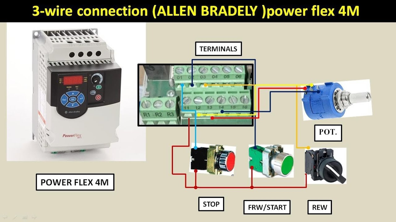
Power Flex 4M Vfd 3 Wire Connection And Programming YouTube
The image title is Power Flex 4M Vfd 3 Wire Connection And Programming YouTube, features dimensions of width 1280 px and height 720 px, with a file size of 1280 x 720 px. This image image/jpeg type visual are source from www.youtube.com.
PowerFlex 525 Parameter Input And Output Programming Tutorial In RSLogix Studio 5000
The image title is PowerFlex 525 Parameter Input And Output Programming Tutorial In RSLogix Studio 5000, features dimensions of width 1600 px and height 626 px, with a file size of 1600 x 626 px. This image image/png type visual are source from www.solisplc.com.
Enabling Safe Torque Off Wiring Safe Torque Off Operation Allen Bradley PowerFlex 525 User Manual Page 211 ManualsLib
The image title is Enabling Safe Torque Off Wiring Safe Torque Off Operation Allen Bradley PowerFlex 525 User Manual Page 211 ManualsLib, features dimensions of width 900 px and height 900 px, with a file size of 900 x 900. This image image/jpeg type visual are source from www.manualslib.com.
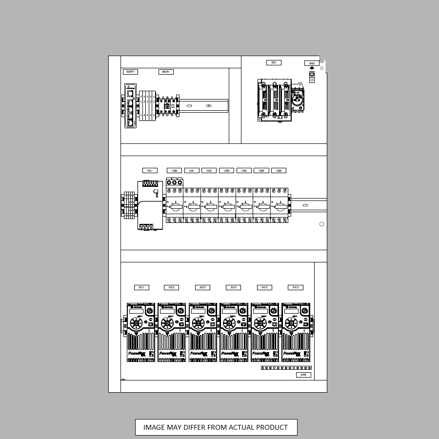
Powerflex 525 Allen Bradley Automation Ready Panels
The image title is Powerflex 525 Allen Bradley Automation Ready Panels, features dimensions of width 900 px and height 900 px, with a file size of 900 x 900. This image image/png type visual are source from www.automationreadypanels.com.
PowerFlex 525 AC Drive Study Notes Design Docsity
The image title is PowerFlex 525 AC Drive Study Notes Design Docsity, features dimensions of width 1280 px and height 1656 px, with a file size of 1280 x 1656. This image image/png type visual are source from www.docsity.com
Powerflex 525 Allen Bradley Automation Ready Panels
The image title is Powerflex 525 Allen Bradley Automation Ready Panels, features dimensions of width 900 px and height 900 px, with a file size of 900 x 900. This image image/png type visual are source from www.automationreadypanels.com.
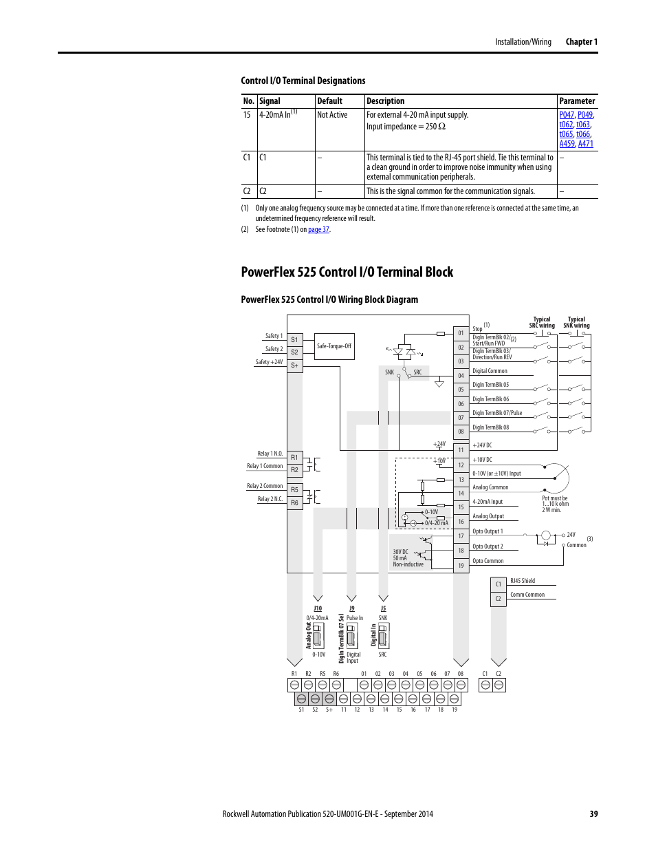
Powerflex 525 User Manual Aslea
The image title is Powerflex 525 User Manual Aslea, features dimensions of width 954 px and height 1235 px, with a file size of 954 x 1235. This image image/png type visual are source from aslea.weebly.com.
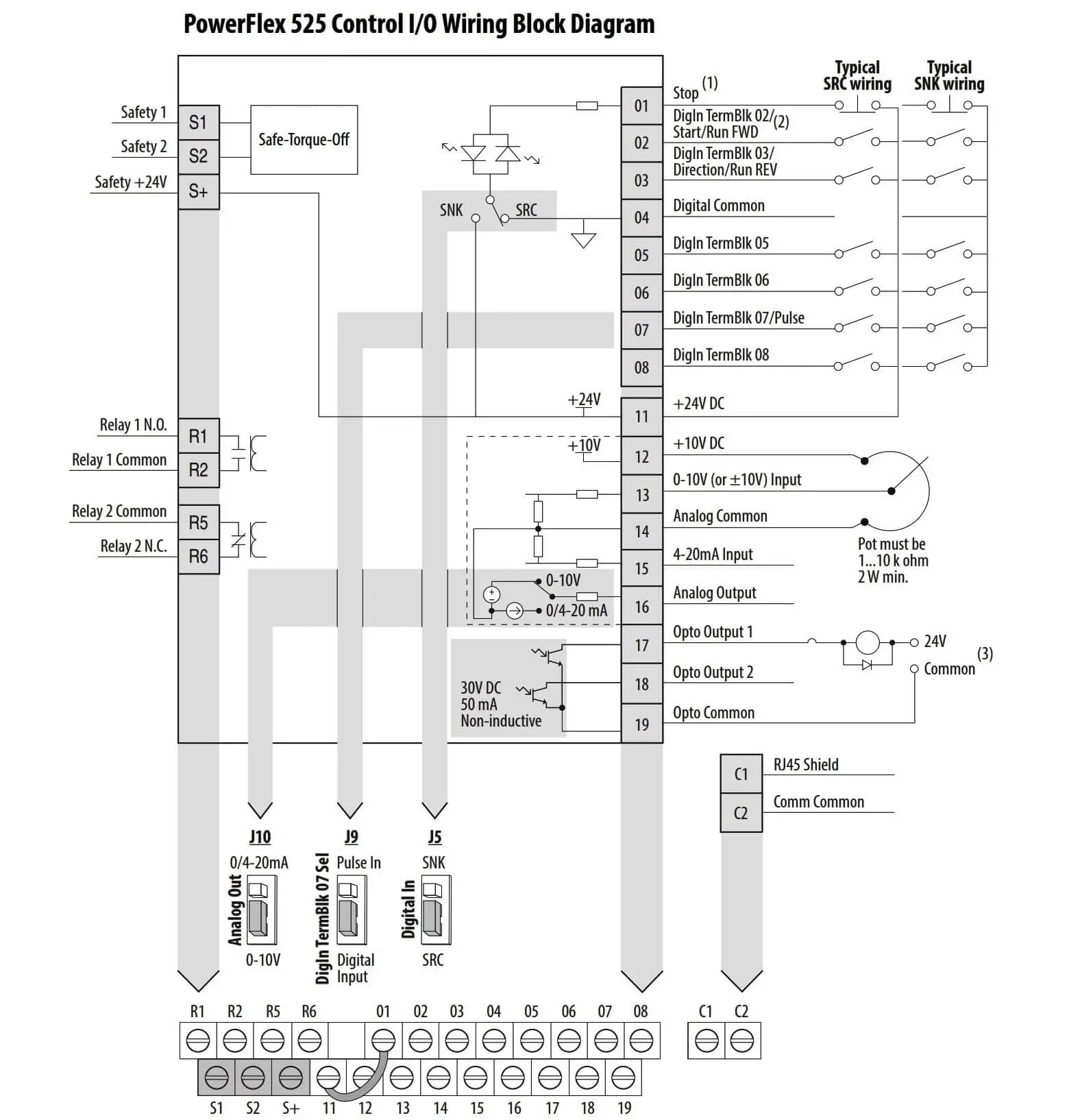
Allen Bradley Powerflex VFD InstrumentationTools
The image title is Allen Bradley Powerflex VFD InstrumentationTools, features dimensions of width 1576 px and height 1634 px, with a file size of 1576 x 1634.
The images on this page, sourced from Google for educational purposes, may be copyrighted. If you own an image and wish its removal or have copyright concerns, please contact us. We aim to promptly address these issues in compliance with our copyright policy and DMCA standards. Your cooperation is appreciated.
Related Keywords to Powerflex 525 Wiring Diagram:
pf 525 wiring diagram,powerflex 525 connection diagram,powerflex 525 wiring diagram,powerflex 525 wiring diagram dwg,powerflex 525 wiring diagram pdf


