Table of Contents
The Ultimate Guide to Potentiometer Wiring Diagram
The Ultimate Guide to Potentiometer Wiring Diagram
Potentiometers are essential components in electronic circuits, allowing for variable resistance and precise control over electrical devices. Understanding how to wire a potentiometer correctly is crucial for ensuring the smooth operation of various electronic applications. In this comprehensive guide, we will delve into the intricacies of potentiometer wiring diagrams, exploring different configurations, applications, and troubleshooting tips to help you master the art of potentiometer connections.
1. Basics of Potentiometer Wiring
Before delving into the specifics of potentiometer wiring diagrams, it is essential to grasp the fundamental principles behind these versatile components. A potentiometer, also known as a pot, is a three-terminal resistor with a rotating or sliding contact that forms an adjustable voltage divider. By varying the resistance using the potentiometer’s knob or slider, users can control the current flow in a circuit, adjust the volume of audio equipment, or dim the intensity of lights.
1.1 Types of Potentiometers
There are various types of potentiometers available, including rotary potentiometers, slide potentiometers, and trimmer potentiometers. Each type serves a specific purpose and comes with its unique wiring configuration. Understanding the differences between these potentiometer variants is crucial for selecting the right one for your application and wiring it correctly.
1.2 Components of a Potentiometer
A potentiometer consists of three terminals: the input terminal, the output terminal, and the wiper terminal. The input terminal is connected to the power source, while the output terminal is linked to the load. The wiper terminal acts as the adjustable contact point, allowing users to vary the resistance and control the output voltage. Properly identifying these terminals is vital for correctly wiring a potentiometer in various circuits.
2. Potentiometer Wiring Diagram Configurations
Potentiometers can be wired in different configurations, depending on the desired application and circuit requirements. Common potentiometer wiring diagrams include voltage divider circuits, rheostat configurations, and variable resistor setups. Each wiring scheme offers unique advantages and is tailored to specific use cases, such as audio volume control, motor speed adjustment, or sensor calibration.
2.1 Voltage Divider Circuit
In a voltage divider circuit, the potentiometer is connected between the power source and ground, with the output voltage taken from the wiper terminal. This configuration allows for precise voltage control and is commonly used in audio equipment, lighting systems, and sensor interfaces.
2.2 Rheostat Configuration
When configured as a rheostat, the potentiometer functions as a variable resistor by using only two terminals. The input and output terminals are connected to form a resistive path, allowing users to adjust the resistance and control the current flow in the circuit. Rheostat setups are ideal for motor speed control, heat regulation, and LED dimming applications.
3. Applications of Potentiometer Wiring
Potentiometers find widespread use in various electronic devices and systems, thanks to their versatility and precision control capabilities. From audio volume knobs and light dimmers to temperature sensors and motor speed controllers, potentiometer wiring plays a critical role in tailoring the performance of these applications to meet specific user requirements.
3.1 Audio Equipment
Potentiometers are commonly used in audio equipment to adjust the volume, tone, and balance of sound output. By wiring potentiometers in audio circuits, users can fine-tune the audio levels, equalization settings, and stereo imaging to create a personalized listening experience.
3.2 Lighting Systems
In lighting systems, potentiometers are utilized to dim or brighten the intensity of lights, providing ambient lighting control in homes, offices, and commercial spaces. By adjusting the resistance of the potentiometer, users can set the desired light output and create the desired ambiance for different settings.
4. Troubleshooting Potentiometer Wiring Issues
Despite their simplicity, potentiometers can encounter wiring problems that affect their performance and reliability. Common issues such as poor connections, faulty terminals, and worn-out resistive tracks can lead to erratic behavior or total failure of the potentiometer. By following proper wiring practices, conducting regular maintenance, and troubleshooting potential problems, users can ensure the optimal functioning of potentiometers in their circuits.
4.1 Tips for Troubleshooting Potentiometer Wiring
Inspect the wiring connections for loose or damaged terminals.
Clean the resistive track of the potentiometer to remove dirt or debris.
Test the potentiometer with a multimeter to check for proper resistance values.
Replace worn-out potentiometers with new units to restore optimal performance.
4.2 Common Potentiometer Wiring Problems
Scratchy or noisy potentiometer operation.
Inconsistent voltage output from the potentiometer.
Intermittent connectivity issues due to loose wiring connections.
Physical damage to the potentiometer casing or terminals.
By addressing these common potentiometer wiring problems promptly and implementing preventive maintenance measures, users can ensure the reliable operation of potentiometers in their circuits and electronic devices.
Related to Potentiometer Wiring Diagram
- Pontoon Boat Wiring Diagram
- Pool Pump Timer Wiring Diagram
- Pool Pump Wiring Diagram
- Portable Generator Wiring Diagram
- Potential Relay Wiring Diagram
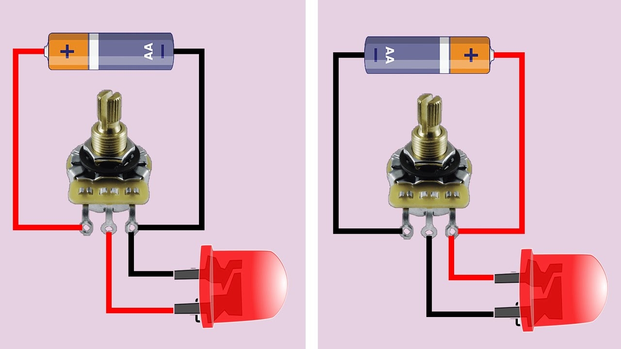
All About Potentiometer Potentiometer Connection Working Circuit Diagram Wiring Guide YouTube
The image title is All About Potentiometer Potentiometer Connection Working Circuit Diagram Wiring Guide YouTube, features dimensions of width 1280 px and height 720 px, with a file size of 1280 x 720 px. This image image/jpeg type visual are source from www.youtube.com.
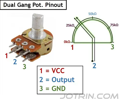
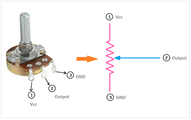
Potentiometer Pinout Symbol Wiring And Working JOTRIN ELECTRONICS
The image title is Potentiometer Pinout Symbol Wiring And Working JOTRIN ELECTRONICS, features dimensions of width 493 px and height 421 px, with a file size of 493 x 421 px. This image image/png type visual are source from www.jotrin.de.
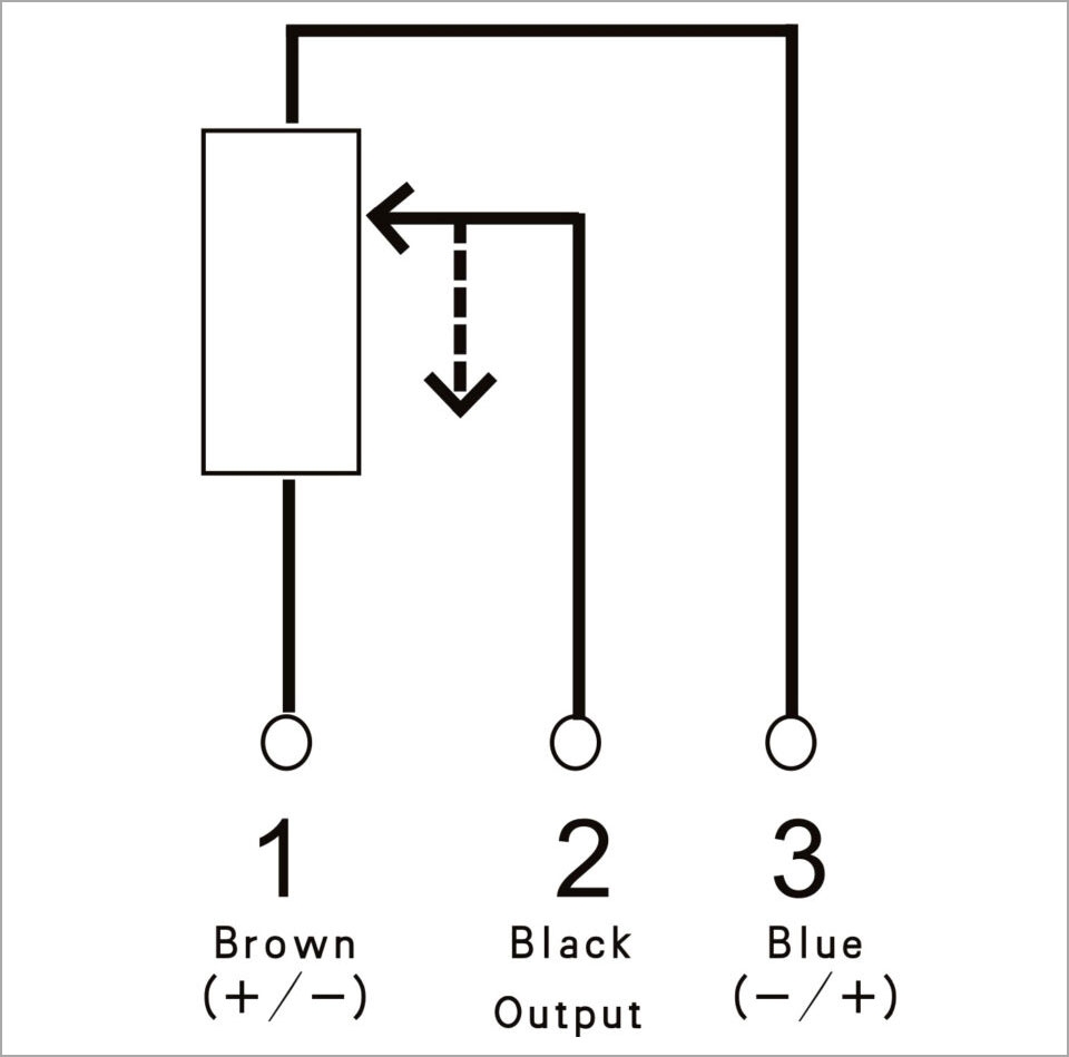
Potentiometer Wiring A Comprehensive Guide
The image title is Potentiometer Wiring A Comprehensive Guide, features dimensions of width 960 px and height 949 px, with a file size of 960 x 949. This image image/jpeg type visual are source from www.nextpcb.com.
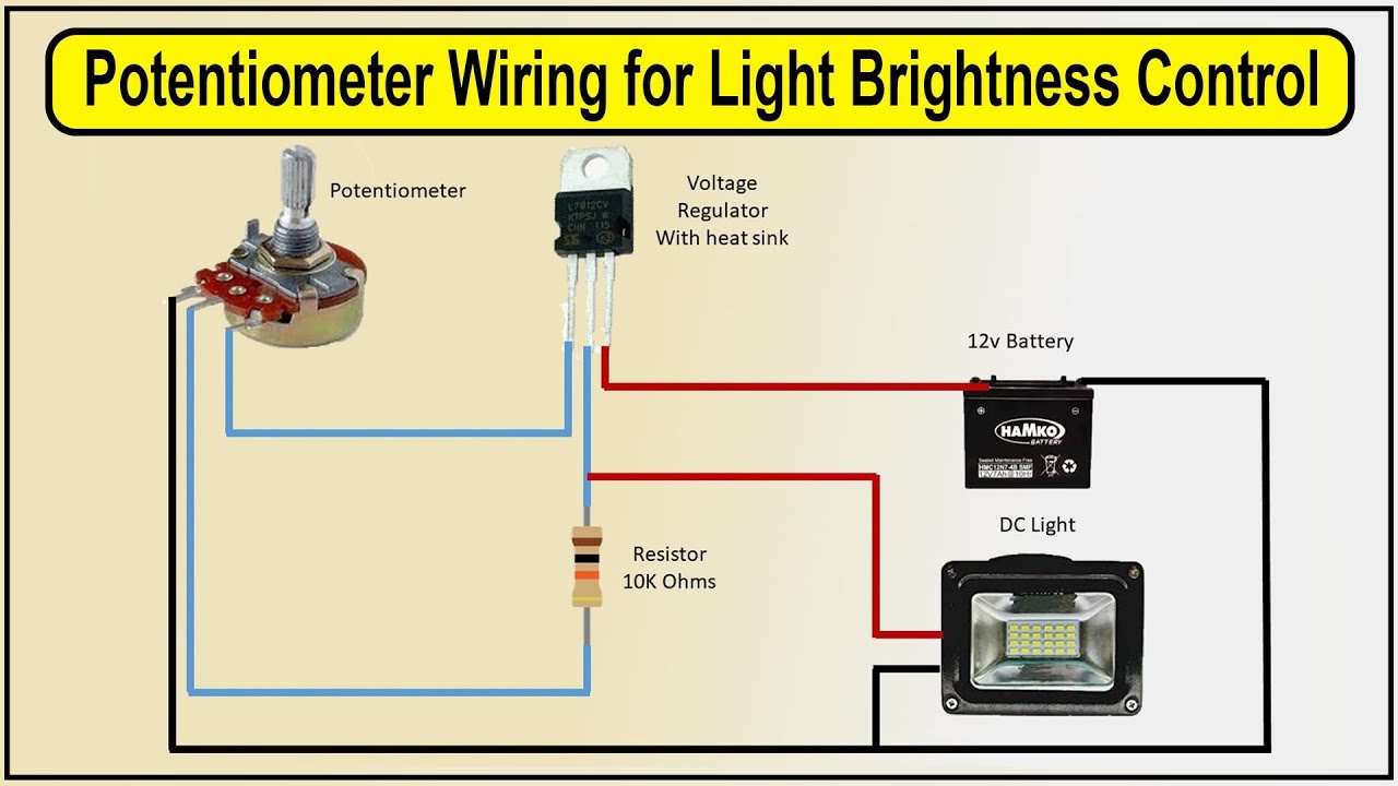
Potentiometer Wiring For Light Brightness Control LED Potentiometer YouTube
The image title is Potentiometer Wiring For Light Brightness Control LED Potentiometer YouTube, features dimensions of width 1280 px and height 720 px, with a file size of 1280 x 720. This image image/jpeg type visual are source from www.youtube.com.
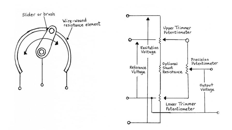
Potentiometers Basic Principles
The image title is Potentiometers Basic Principles, features dimensions of width 960 px and height 540 px, with a file size of 960 x 540. This image image/jpeg type visual are source from epci.eu
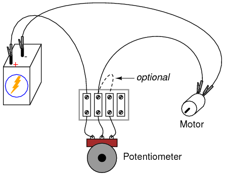
Power Supply Wiring A Potentiometer For A Positive Voltage Electrical Engineering Stack Exchange
The image title is Power Supply Wiring A Potentiometer For A Positive Voltage Electrical Engineering Stack Exchange, features dimensions of width 445 px and height 348 px, with a file size of 445 x 348. This image image/png type visual are source from electronics.stackexchange.com.
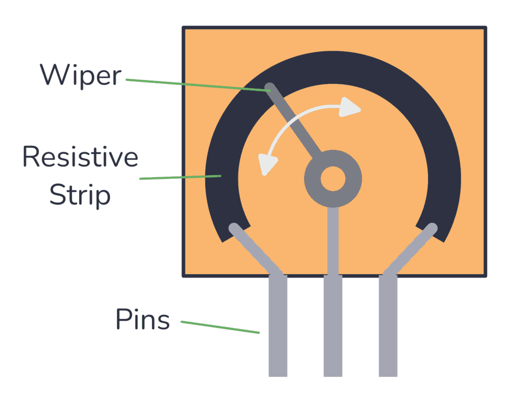
The Potentiometer Pinout Wiring And How It Works
The image title is The Potentiometer Pinout Wiring And How It Works, features dimensions of width 1024 px and height 793 px, with a file size of 1024 x 793. This image image/png type visual are source from www.build-electronic-circuits.com.
Potentiometer Circuit Circuit Diagram Electronics Basics Electronic Circuit Projects
The image title is Potentiometer Circuit Circuit Diagram Electronics Basics Electronic Circuit Projects, features dimensions of width 640 px and height 404 px, with a file size of 640 x 404.
The images on this page, sourced from Google for educational purposes, may be copyrighted. If you own an image and wish its removal or have copyright concerns, please contact us. We aim to promptly address these issues in compliance with our copyright policy and DMCA standards. Your cooperation is appreciated.
Related Keywords to Potentiometer Wiring Diagram:
pot wiring diagram,potentiometer wiring diagram,potentiometer wiring diagram 3 pin,potentiometer wiring diagram arduino,potentiometer wiring diagram pdf
