Table of Contents
The Value of Plc Wiring Diagrams
Plc wiring diagrams serve as the blueprint for industrial automation systems, providing a visual representation of how various components are interconnected to ensure seamless operation. These diagrams are crucial for engineers, technicians, and electricians involved in designing, installing, and troubleshooting Programmable Logic Controllers (PLCs). Understanding the intricacies of PLC wiring diagrams is essential for ensuring the efficiency, safety, and reliability of automated processes in manufacturing plants, refineries, and other industrial settings.
The Basics of Plc Wiring Diagrams
At the core of a PLC wiring diagram are symbols representing different components such as relays, switches, sensors, and actuators. These symbols are interconnected using lines to depict the electrical connections between them. By following these connections, technicians can identify the logic of the control system and diagnose any issues that may arise during operation. A well-organized and clearly labeled PLC wiring diagram can simplify the commissioning and maintenance of automation systems, saving time and reducing the risk of errors.
Key Components in Plc Wiring Diagrams
- Input modules: These components receive signals from sensors and switches, transmitting them to the PLC for processing.
- Output modules: Responsible for controlling actuators such as motors, valves, and solenoids based on the instructions from the PLC.
- Power supply: Provides the necessary voltage to operate the PLC and its associated components.
- Communication modules: Enable data exchange between the PLC and external devices such as HMI panels, SCADA systems, and other controllers.
Benefits of Using Plc Wiring Diagrams
Efficiently designed and accurately documented PLC wiring diagrams offer several advantages to industrial automation professionals:
- Enhanced troubleshooting: Clear visualization of the control system’s logic simplifies the identification and resolution of wiring errors or malfunctions.
- Streamlined maintenance: Access to up-to-date wiring diagrams facilitates quick repairs and modifications, minimizing downtime and production losses.
- Compliance with standards: Following established wiring diagram conventions ensures adherence to industry regulations and safety guidelines.
Tips for Creating Effective Plc Wiring Diagrams
- Use standardized symbols and labels for consistency and clarity.
- Include a legend or key to explain the meaning of each symbol used in the diagram.
- Organize components logically to reflect the physical layout of the control system.
- Update wiring diagrams whenever modifications are made to the PLC system to maintain accuracy.
In conclusion, Plc wiring diagrams play a vital role in the successful implementation of automation solutions in industrial environments. By understanding the fundamentals of these diagrams and leveraging them effectively, professionals can ensure the smooth operation of PLC systems, optimize maintenance processes, and enhance overall productivity.
Related to Plc Wiring Diagram
- Pioneer Wiring Harness Diagram
- Pioneer Wiring Harness Diagram 16 Pin
- Pit Boss Wiring Diagram
- Pj Bass Wiring Diagram
- Pj Trailer Wiring Diagram
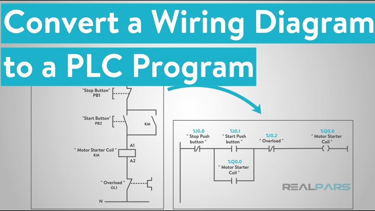
How To Convert A Basic Wiring Diagram To A PLC Program RealPars
The image title is How To Convert A Basic Wiring Diagram To A PLC Program RealPars, features dimensions of width 1230 px and height 679 px, with a file size of 1230 x 679 px. This image image/gif type visual are source from www.realpars.com.
How To Read Electrical Schematics 8 PLC Controller Part 1 2 Blog Related To Industrial Automation PLC HMI Control Systems
The image title is How To Read Electrical Schematics 8 PLC Controller Part 1 2 Blog Related To Industrial Automation PLC HMI Control Systems, features dimensions of width 1104 px and height 767 px, with a file size of 1104 x 767 px. This image image/jpeg type visual are source from automationtop.com.
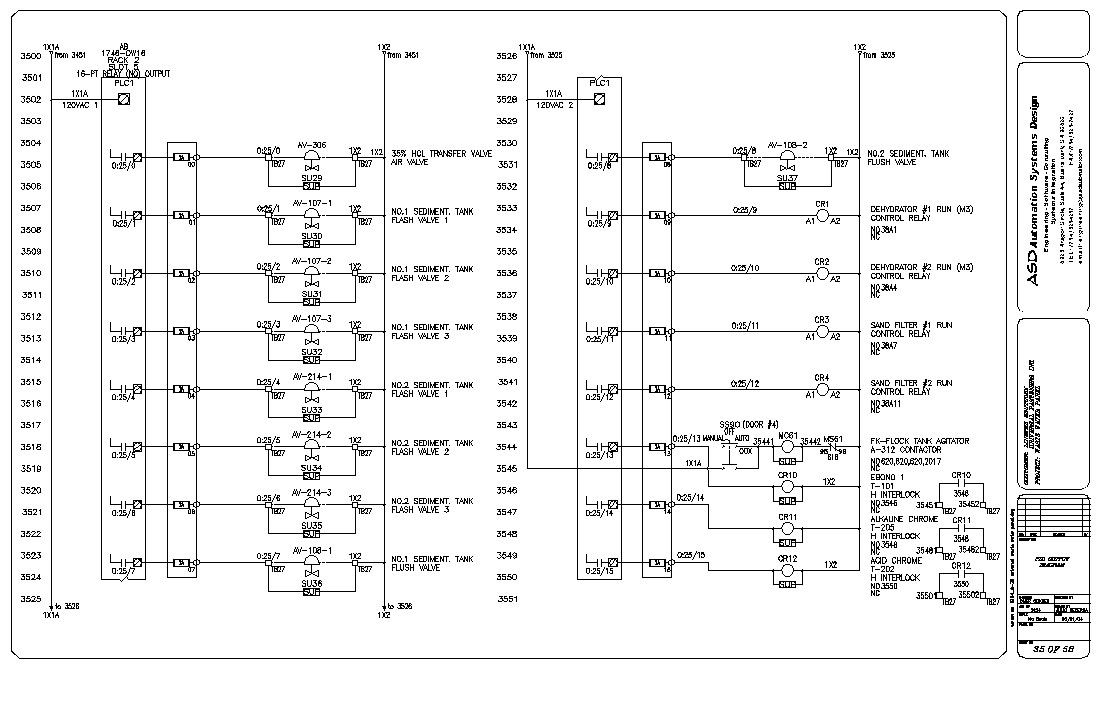
Plc Control Panel Wiring Diagram On Plc Panel Wiring Diagram Electrical Circuit Diagram Circuit Diagram Ladder Logic
The image title is Plc Control Panel Wiring Diagram On Plc Panel Wiring Diagram Electrical Circuit Diagram Circuit Diagram Ladder Logic, features dimensions of width 1103 px and height 714 px, with a file size of 1103 x 714. This image image/jpeg type visual are source from hu.pinterest.com.
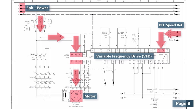
How To Read Plc Diagram Archives Upmation
The image title is How To Read Plc Diagram Archives Upmation, features dimensions of width 794 px and height 447 px, with a file size of 794 x 447. This image image/jpeg type visual are source from upmation.com.
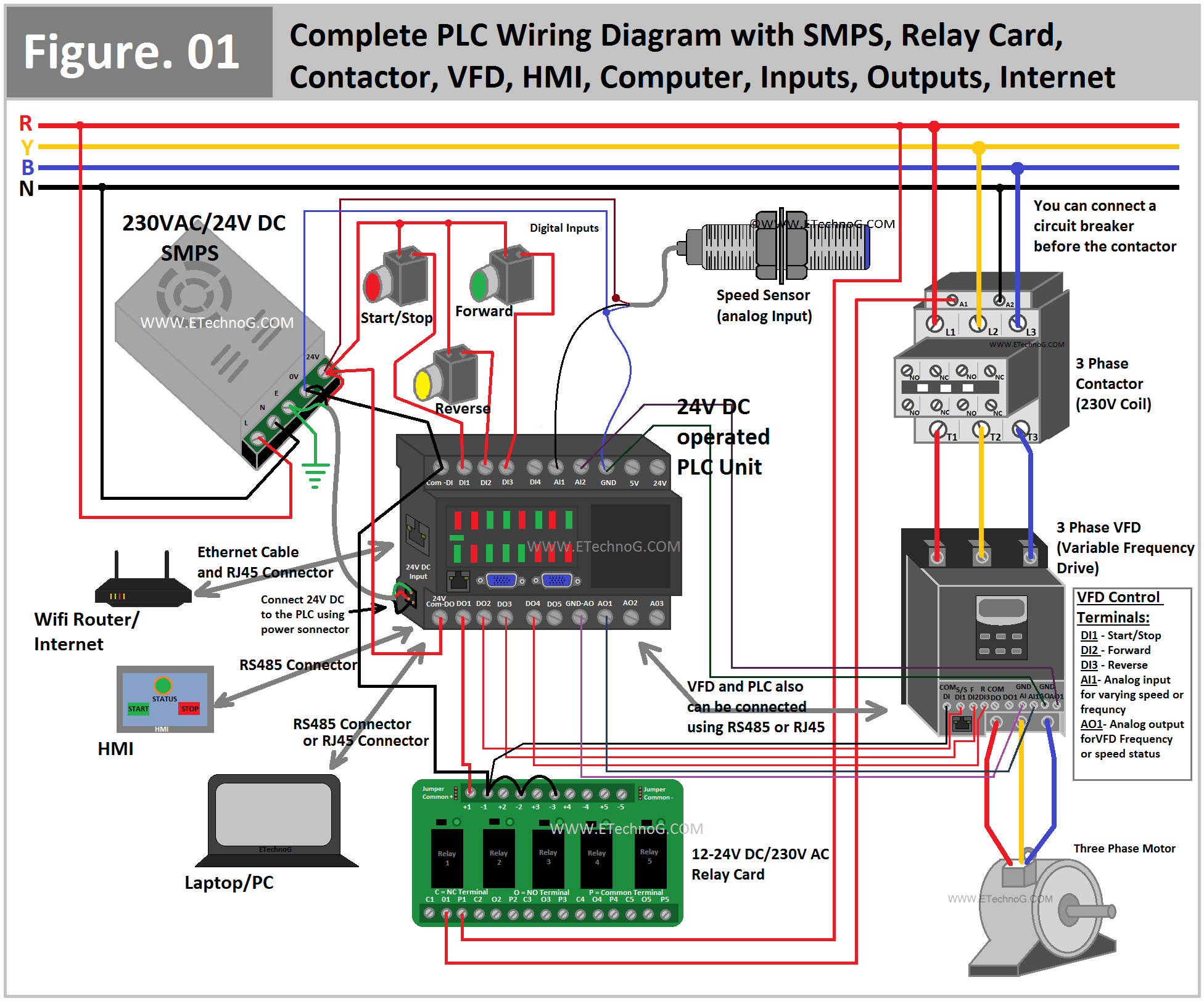
Complete PLC Wiring Diagram With SMPS Relay Card Contactor Programmable Logic Controller Electrical Circuit Diagram Ethernet Wiring
The image title is Complete PLC Wiring Diagram With SMPS Relay Card Contactor Programmable Logic Controller Electrical Circuit Diagram Ethernet Wiring, features dimensions of width 1952 px and height 1624 px, with a file size of 1952 x 1624. This image image/png type visual are source from www.pinterest.com
How To Convert A Basic Wiring Diagram To A PLC Program YouTube
The image title is How To Convert A Basic Wiring Diagram To A PLC Program YouTube, features dimensions of width 1280 px and height 720 px, with a file size of 1280 x 720. This image image/jpeg type visual are source from www.youtube.com.
How To Read Plc Diagram Archives Upmation
The image title is How To Read Plc Diagram Archives Upmation, features dimensions of width 795 px and height 447 px, with a file size of 795 x 447. This image image/jpeg type visual are source from upmation.com.
Wiring In A PLC Control Panel Basic Electrical Design
The image title is Wiring In A PLC Control Panel Basic Electrical Design, features dimensions of width 1922 px and height 1163 px, with a file size of 1922 x 1163.
The images on this page, sourced from Google for educational purposes, may be copyrighted. If you own an image and wish its removal or have copyright concerns, please contact us. We aim to promptly address these issues in compliance with our copyright policy and DMCA standards. Your cooperation is appreciated.
Related Keywords to Plc Wiring Diagram:
plc wiring diagram,plc wiring diagram examples,plc wiring diagram pdf,plc wiring diagram symbols,plc wiring diagram symbols pdf


