Table of Contents
The Ultimate Guide to Motor Starter Wiring Diagram
Motor starter wiring diagrams serve as the blueprint for connecting electrical components in a motor control circuit. Understanding these diagrams is crucial for electricians, engineers, and anyone working with industrial machinery. Whether you’re troubleshooting an existing setup or installing a new motor starter, having a solid grasp of wiring diagrams is essential. Let’s delve into the intricacies of motor starter wiring diagrams to unravel the complexities and streamline the process.
Importance of Motor Starter Wiring Diagram
A motor starter wiring diagram is like a roadmap that guides you through the intricate network of electrical connections within a motor control system. It provides a visual representation of how various components such as contactors, overload relays, and push buttons are interconnected to start, stop, and protect the motor. By following the wiring diagram accurately, you can ensure proper functionality, prevent electrical faults, and troubleshoot issues effectively.
Components of Motor Starter Wiring Diagram
Before diving into the intricacies of wiring diagrams, it’s essential to familiarize yourself with the key components typically found in motor starter circuits:
- Contactors: These electromechanical switches control the flow of electricity to the motor.
- Overload Relays: Protect the motor from excessive current by tripping when the load exceeds the set limit.
- Start/Stop Buttons: Allow operators to initiate or halt motor operation manually.
- Control Transformers: Step down voltage to power control circuits safely.
Understanding Wiring Symbols
Wiring diagrams use standardized symbols to represent various electrical components and connections. Familiarizing yourself with these symbols is crucial for interpreting diagrams accurately. Some common symbols include:
- Coil Symbol: Represents coils of contactors or relays.
- Contact Symbol: Indicate the contacts of switches or relays.
- Ground Symbol: Denotes the connection to ground for safety.
- Wire Connections: Show how wires are connected, including splices, branches, and junctions.
Interpreting Motor Starter Wiring Diagrams
When examining a motor starter wiring diagram, it’s essential to follow a systematic approach to ensure accurate interpretation and implementation. Here are some key steps to help you navigate through the diagram effectively:
- Identify Power Supply: Locate the power source and understand how it feeds into the motor starter circuit.
- Follow Control Logic: Trace the path of control signals from the start/stop buttons to the contactors and relays.
- Check Safety Devices: Ensure that overload relays and other protective devices are correctly integrated into the circuit.
- Verify Grounding: Confirm proper grounding connections to prevent electrical hazards.
By following these steps and understanding the wiring diagram in detail, you can troubleshoot faults, install new equipment, and maintain motor control systems with confidence.
Conclusion
Mastering motor starter wiring diagrams is a valuable skill that empowers individuals to work efficiently with motor control systems. By grasping the fundamentals of these diagrams, you can ensure safe and effective operation of motors in various industrial applications. Remember, a well-executed wiring diagram is not just a technical necessity but a roadmap to success in the realm of electrical engineering.
Related to Motor Starter Wiring Diagram
- Mobile Home Wiring Diagrams
- Monoblock Amp Wiring Diagram
- Moped Taotao 50cc Scooter Wiring Diagram
- Motion Sensor Light Wiring Diagram
- Motion Sensor Wiring Diagram
Motor Starter Wiring Diagram
The image title is Motor Starter Wiring Diagram, features dimensions of width 640 px and height 377 px, with a file size of 640 x 377 px. This image image/jpeg type visual are source from compressors.tpub.com.
Acceptable Starter Motor Wiring With Mag Switch
The image title is Acceptable Starter Motor Wiring With Mag Switch, features dimensions of width 1048 px and height 799 px, with a file size of 1048 x 799 px. This image image/jpeg type visual are source from www.sbmar.com.
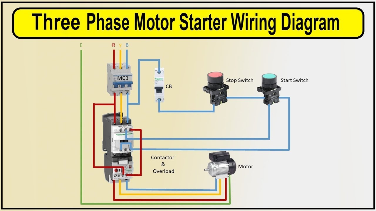
How To Make 3 Phase Motor Starter Wiring Diagram 3 Phase Motor Contactor Wiring Diagram YouTube
The image title is How To Make 3 Phase Motor Starter Wiring Diagram 3 Phase Motor Contactor Wiring Diagram YouTube, features dimensions of width 1280 px and height 720 px, with a file size of 1280 x 720. This image image/jpeg type visual are source from www.youtube.com.
Basic Wiring For Motor Control Technical Data Guide EEP
The image title is Basic Wiring For Motor Control Technical Data Guide EEP, features dimensions of width 378 px and height 242 px, with a file size of 378 x 242. This image image/gif type visual are source from electrical-engineering-portal.com.
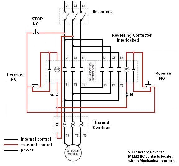
Motor Starter Wiring Diagrams VintageMachinery Knowledge Base Wiki
The image title is Motor Starter Wiring Diagrams VintageMachinery Knowledge Base Wiki, features dimensions of width 576 px and height 535 px, with a file size of 576 x 535. This image image/jpeg type visual are source from wiki.vintagemachinery.org
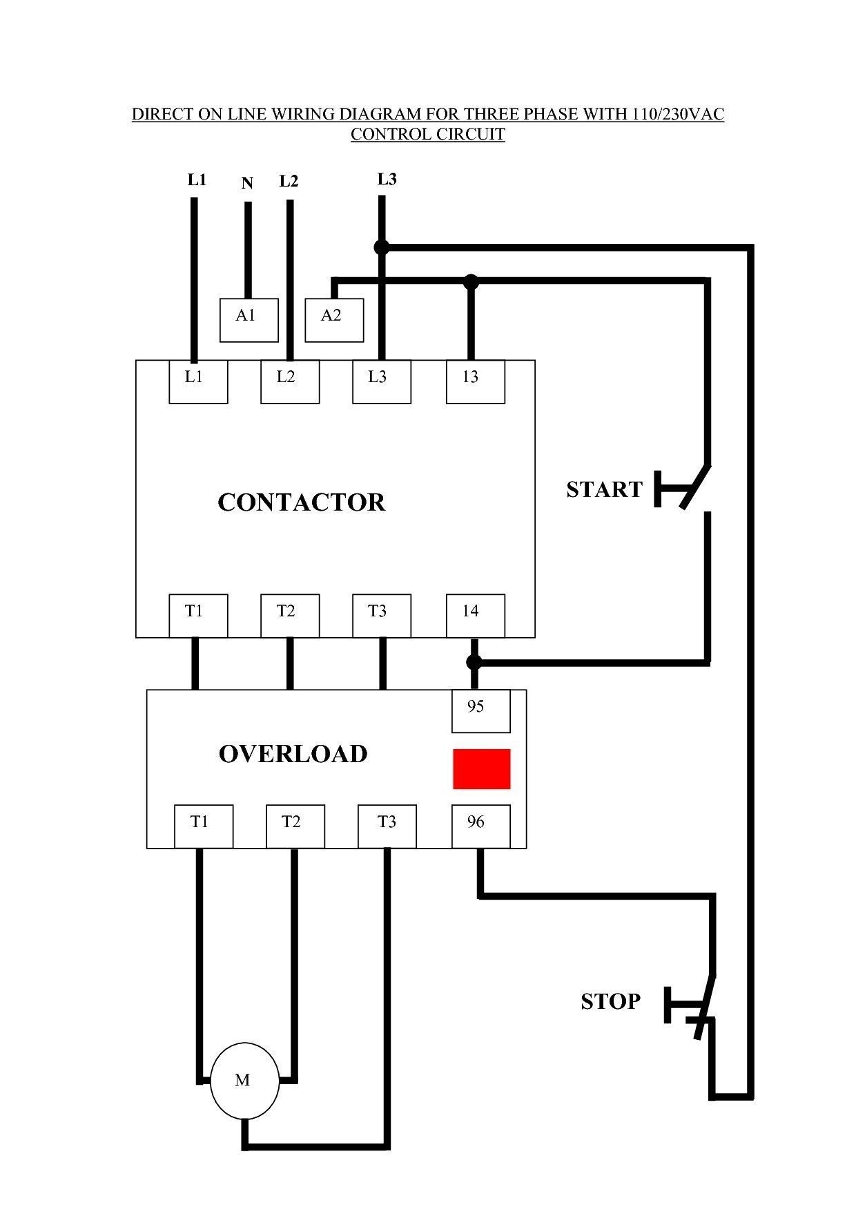
60 Beautiful Motor Starter Wiring Diagram Electrical Circuit Diagram Circuit Diagram Electrical Wiring Diagram
The image title is 60 Beautiful Motor Starter Wiring Diagram Electrical Circuit Diagram Circuit Diagram Electrical Wiring Diagram, features dimensions of width 1240 px and height 1754 px, with a file size of 1240 x 1754. This image image/jpeg type visual are source from www.pinterest.com.
Basic Wiring For Motor Control Technical Data Guide EEP
The image title is Basic Wiring For Motor Control Technical Data Guide EEP, features dimensions of width 313 px and height 308 px, with a file size of 313 x 308. This image image/gif type visual are source from electrical-engineering-portal.com.
Motor Starter Wiring Diagrams VintageMachinery Knowledge Base Wiki Electrical Circuit Diagram Basic Electrical Engineering Diagram
The image title is Motor Starter Wiring Diagrams VintageMachinery Knowledge Base Wiki Electrical Circuit Diagram Basic Electrical Engineering Diagram, features dimensions of width 576 px and height 477 px, with a file size of 576 x 477.
The images on this page, sourced from Google for educational purposes, may be copyrighted. If you own an image and wish its removal or have copyright concerns, please contact us. We aim to promptly address these issues in compliance with our copyright policy and DMCA standards. Your cooperation is appreciated.
Related Keywords to Motor Starter Wiring Diagram:
motor starter wiring diagram,motor starter wiring diagram 3 phase,motor starter wiring diagram pdf,motor starter wiring diagram start stop,motor starter wiring diagram with hoa


