Table of Contents
Exploring the Value of Intermatic Timer Wiring Diagram
When it comes to electrical installations and maintenance, having a clear understanding of wiring diagrams is crucial. In the world of timers, the Intermatic brand stands out for its reliability and efficiency. Intermatic timer wiring diagrams serve as invaluable tools for electricians and DIY enthusiasts alike, offering a detailed roadmap for connecting and configuring timers with precision. Let’s delve into the world of Intermatic timer wiring diagrams to unravel their significance and explore the intricate details they provide.
The Basics of Intermatic Timer Wiring Diagram
Intermatic timer wiring diagrams are comprehensive visual representations that outline the connections and configurations required for proper timer operation. These diagrams typically include detailed information on wiring terminals, input/output connections, voltage requirements, and programming options. By following these diagrams diligently, users can ensure that their Intermatic timers function correctly and reliably.
Key Components of Intermatic Timer Wiring Diagram
- Terminal Identification: Each terminal on the timer is labeled for easy reference in the wiring diagram.
- Connection Points: The diagram specifies where wires should be connected to ensure proper functionality.
- Voltage Requirements: Information on voltage input/output is crucial for safe and efficient operation.
- Programming Details: Timers may have specific programming options that are detailed in the wiring diagram.
Benefits of Using Intermatic Timer Wiring Diagrams
Utilizing Intermatic timer wiring diagrams offers several advantages for both professionals and beginners in the field of electrical work. Some of the key benefits include:
- Accuracy: Following a precise wiring diagram reduces the risk of errors and ensures a successful installation.
- Efficiency: With clear instructions provided in the diagram, the installation process becomes quicker and more efficient.
- Troubleshooting: In case of issues or malfunctions, the wiring diagram serves as a valuable reference for troubleshooting and repairs.
- Standardization: Intermatic timer wiring diagrams follow industry standards, promoting consistency in installations.
Exploring Advanced Features with Intermatic Timer Wiring Diagrams
Beyond the basic wiring connections, Intermatic timer diagrams can also reveal advanced features and functionalities that users can leverage for enhanced performance. These may include:
Multi-Zone Control
Some Intermatic timers support multi-zone control, allowing users to program different schedules for various areas or devices. The wiring diagram illustrates how to configure these zones for tailored automation.
Remote Access
Certain Intermatic timers offer remote access capabilities, enabling users to control their timers from a smartphone or computer. The wiring diagram guides users on setting up the necessary connections for remote access.
Conclusion
In conclusion, Intermatic timer wiring diagrams are indispensable resources for anyone working with timers in electrical systems. By understanding and utilizing these diagrams effectively, users can ensure the proper installation, operation, and maintenance of their Intermatic timers. Whether you are a seasoned professional or a novice enthusiast, harnessing the power of wiring diagrams can elevate your electrical projects to new heights of efficiency and reliability.
Related to Intermatic Timer Wiring Diagram
- Ignition System Wiring Diagram
- Ignition Wiring Diagram
- Ignition Wiring Harley Dual Fire Coil Wiring Diagram
- Indak Ignition Switch Wiring Diagram
- Instruction Metra Line Output Converter Wiring Diagram
How To Wire Intermatic T104 And T103 And T101 Timers
The image title is How To Wire Intermatic T104 And T103 And T101 Timers, features dimensions of width 1876 px and height 986 px, with a file size of 1876 x 986 px. This image image/jpeg type visual are source from waterheatertimer.org.
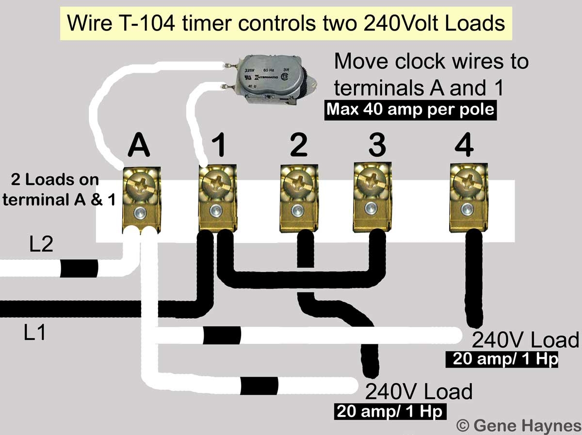
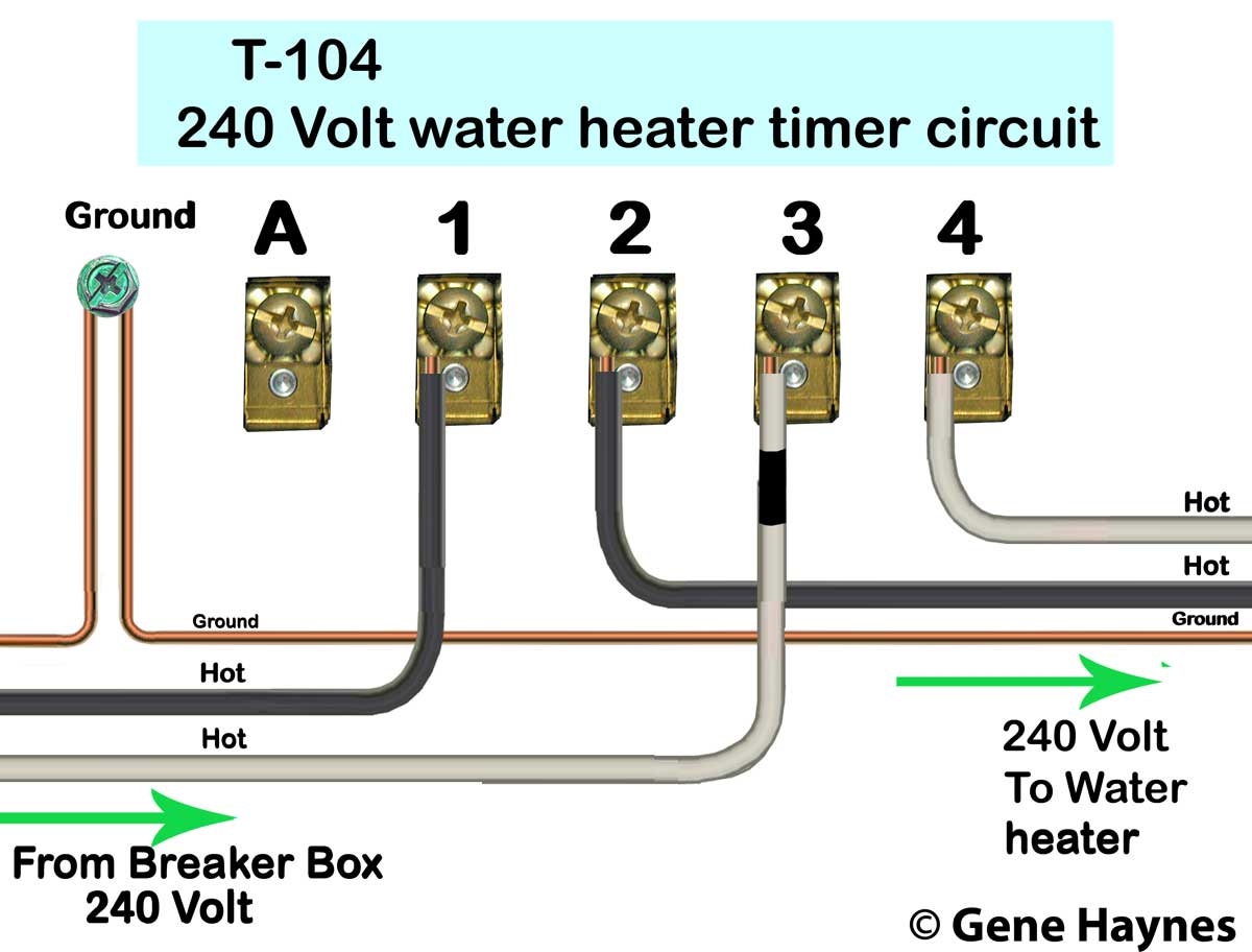
How To Wire Intermatic T104 And T103 And T101 Timers
The image title is How To Wire Intermatic T104 And T103 And T101 Timers, features dimensions of width 1200 px and height 897 px, with a file size of 1200 x 897 px. This image image/jpeg type visual are source from waterheatertimer.org.
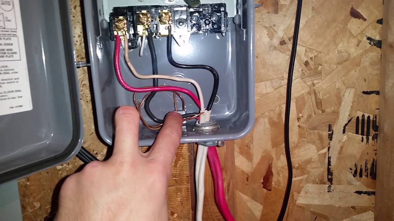
How To Wire And Connect A Intermatic Pool Pump Timer T101R YouTube
The image title is How To Wire And Connect A Intermatic Pool Pump Timer T101R YouTube, features dimensions of width 1280 px and height 720 px, with a file size of 1280 x 720. This image image/jpeg type visual are source from m.youtube.com.
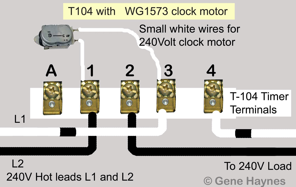
How To Wire Intermatic T104 And T103 And T101 Timers
The image title is How To Wire Intermatic T104 And T103 And T101 Timers, features dimensions of width 1200 px and height 758 px, with a file size of 1200 x 758. This image image/jpeg type visual are source from waterheatertimer.org.
Electrical Identifying Wires In An Intermatic Pool Pump Timer Home Improvement Stack Exchange
The image title is Electrical Identifying Wires In An Intermatic Pool Pump Timer Home Improvement Stack Exchange, features dimensions of width 1186 px and height 1581 px, with a file size of 1186 x 1581. This image image/jpeg type visual are source from diy.stackexchange.com
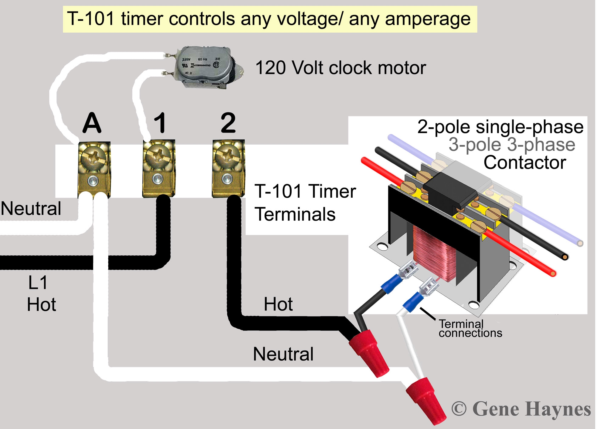
How To Wire T101 Timer
The image title is How To Wire T101 Timer, features dimensions of width 2000 px and height 1415 px, with a file size of 2000 x 1415. This image image/jpeg type visual are source from waterheatertimer.org.
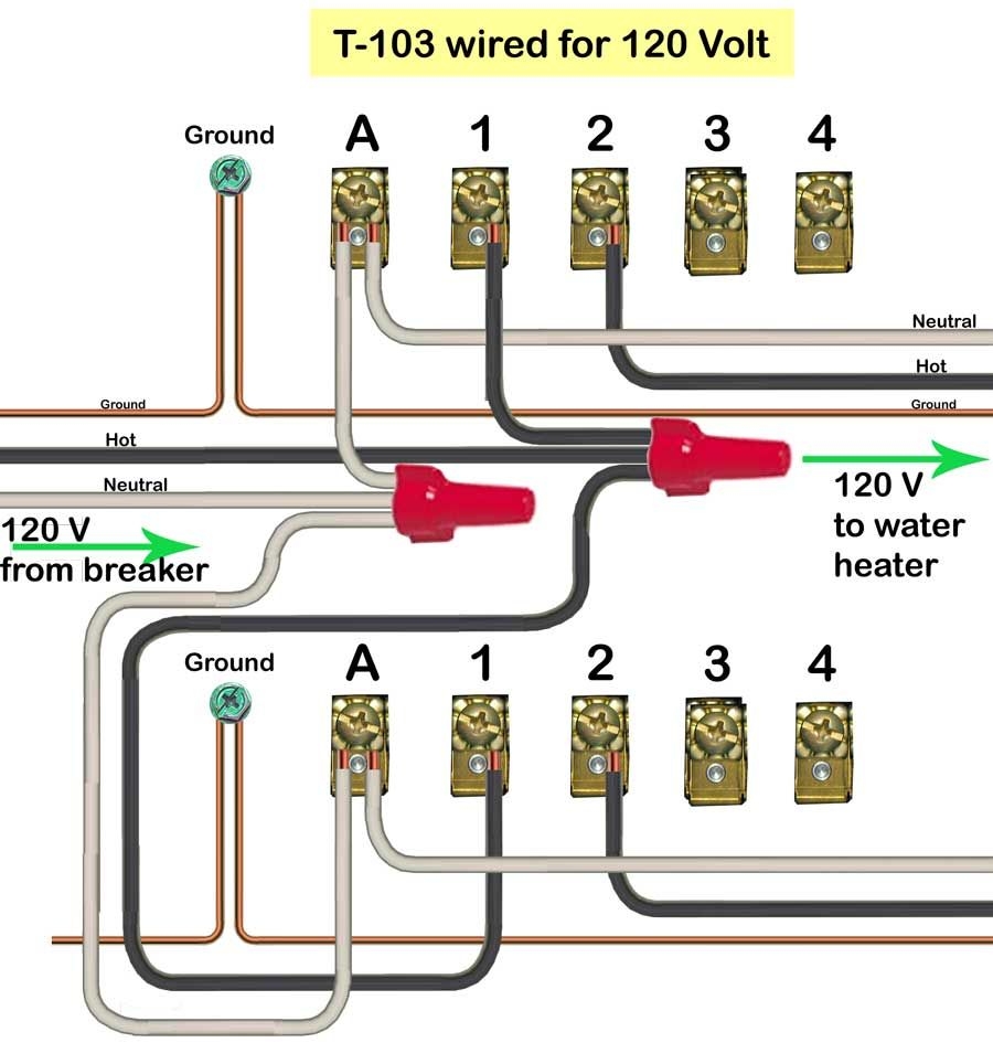
How To Wire Intermatic T104 Timer
The image title is How To Wire Intermatic T104 Timer, features dimensions of width 900 px and height 964 px, with a file size of 900 x 964. This image image/jpeg type visual are source from www.pinterest.com.
How To Wire Intermatic T104 And T103 And T101 Timers
The image title is How To Wire Intermatic T104 And T103 And T101 Timers, features dimensions of width 1200 px and height 912 px, with a file size of 1200 x 912.
The images on this page, sourced from Google for educational purposes, may be copyrighted. If you own an image and wish its removal or have copyright concerns, please contact us. We aim to promptly address these issues in compliance with our copyright policy and DMCA standards. Your cooperation is appreciated.
Related Keywords to Intermatic Timer Wiring Diagram:
intermatic timer wiring diagram,intermatic timer wiring diagram pdf,intermatic timer wiring diagram st01,intermatic timer wiring instructions,intermatic timer wiring schematic

