Table of Contents
Gm Mass Air Flow Sensor Wiring Diagram
The Importance of Gm Mass Air Flow Sensor Wiring Diagram
If you’re a car enthusiast or someone who loves to tinker with engines, understanding the intricacies of your vehicle’s mass air flow sensor wiring diagram is crucial. The GM mass air flow sensor plays a vital role in monitoring the amount of air entering the engine, which in turn affects fuel delivery and overall performance. By delving into the wiring diagram of this essential component, you gain valuable insights into how your car functions and how to troubleshoot any issues that may arise. Let’s explore the world of GM mass air flow sensor wiring diagrams and unravel the mysteries behind this critical automotive component.
Components of Gm Mass Air Flow Sensor
1. Power Supply
The power supply is responsible for providing the necessary voltage for the mass air flow sensor to operate correctly. Understanding how power flows through the wiring diagram ensures that the sensor receives consistent power, optimizing its performance.
2. Ground Connection
A solid ground connection is essential for the mass air flow sensor to accurately measure airflow. By analyzing the wiring diagram, you can identify the grounding points and ensure that there are no issues affecting the sensor’s ability to function properly.
Reading Gm Mass Air Flow Sensor Wiring Diagram
When deciphering a GM mass air flow sensor wiring diagram, it’s essential to pay attention to the color codes, wire paths, and connection points. Each wire serves a specific purpose, and understanding how they interact with the sensor can help you diagnose problems effectively. By following the wiring diagram meticulously, you can trace the flow of electricity and pinpoint any potential issues that may be affecting your sensor’s performance.
Common Issues and Troubleshooting
1. Voltage Fluctuations
One common issue with mass air flow sensors is voltage fluctuations, which can lead to inaccurate readings and poor engine performance. By referring to the wiring diagram, you can check the power supply and ground connections to ensure that voltage levels are stable, allowing the sensor to operate optimally.
2. Wiring Damage
Wiring damage is another prevalent issue that can affect the mass air flow sensor’s functionality. By inspecting the wiring diagram and visually examining the wires, you can identify any signs of wear, corrosion, or breaks that may be disrupting the sensor’s operation. Repairing or replacing damaged wiring can restore proper functionality to the sensor.
Conclusion
In conclusion, delving into the world of GM mass air flow sensor wiring diagrams can provide valuable insights into your vehicle’s performance and help you troubleshoot any issues that may arise. By understanding the components, reading the wiring diagram, and addressing common problems, you can ensure that your mass air flow sensor operates effectively, optimizing your car’s engine performance. So, roll up your sleeves, grab your multimeter, and dive into the intricate world of GM mass air flow sensor wiring diagrams!
Related to Gm Mass Air Flow Sensor Wiring Diagram
- Gm Bose Amp Wiring Diagram
- Gm Fuel Pump Wiring Harness Diagram
- Gm Headlight Switch Wiring Diagram
- Gm Ignition Switch Wiring Diagram
- Gm Maf Sensor Wiring Diagram
MAF Harness Connector Pigtail Plug Mass Airflow Sensor Wiring Fit GM Chevy GMC EBay
The image title is MAF Harness Connector Pigtail Plug Mass Airflow Sensor Wiring Fit GM Chevy GMC EBay, features dimensions of width 400 px and height 251 px, with a file size of 400 x 251 px. This image image/jpeg type visual are source from www.ebay.com.
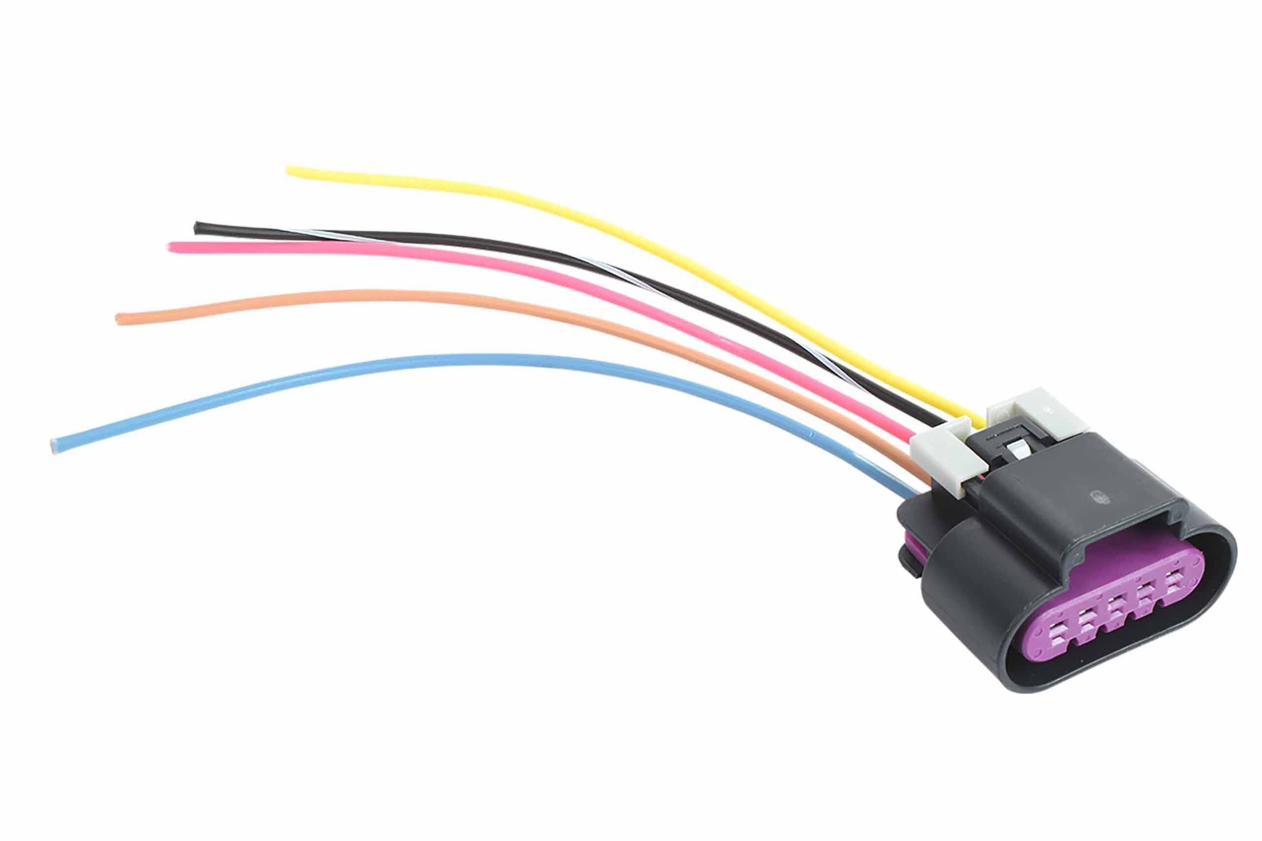
Amazon ICT BIllet LS3 Gen 4 Wire Pigtail Connector MAF 5 Wire Mass Air Flow IAT Intake Air Temperature Sensor Card Style Compatible With GM RPO Codes 6 2 L99 LS WPMAF43 Automotive
The image title is Amazon ICT BIllet LS3 Gen 4 Wire Pigtail Connector MAF 5 Wire Mass Air Flow IAT Intake Air Temperature Sensor Card Style Compatible With GM RPO Codes 6 2 L99 LS WPMAF43 Automotive, features dimensions of width 2560 px and height 1706 px, with a file size of 2560 x 1706 px. This image image/jpeg type visual are source from www.amazon.com.
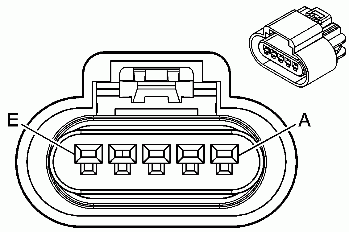
Mass Air Flow Sensor Pigtail Harness PGTL 003 Wiring Splices Pigtails Racetronix
The image title is Mass Air Flow Sensor Pigtail Harness PGTL 003 Wiring Splices Pigtails Racetronix, features dimensions of width 1131 px and height 752 px, with a file size of 1131 x 752. This image image/gif type visual are source from www.racetronix.biz.
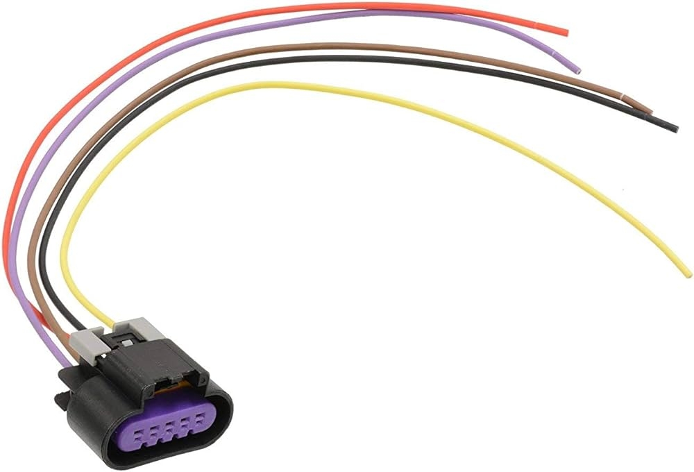
Amazon Michigan Motorsports 5 Wire Mass Air Flow Pigtail MAF For LS3 And LS7 Sensor Wire Harness Fitment Camaro Firebird Vehicles Automotive
The image title is Amazon Michigan Motorsports 5 Wire Mass Air Flow Pigtail MAF For LS3 And LS7 Sensor Wire Harness Fitment Camaro Firebird Vehicles Automotive, features dimensions of width 1000 px and height 680 px, with a file size of 1000 x 680. This image image/jpeg type visual are source from www.amazon.com.
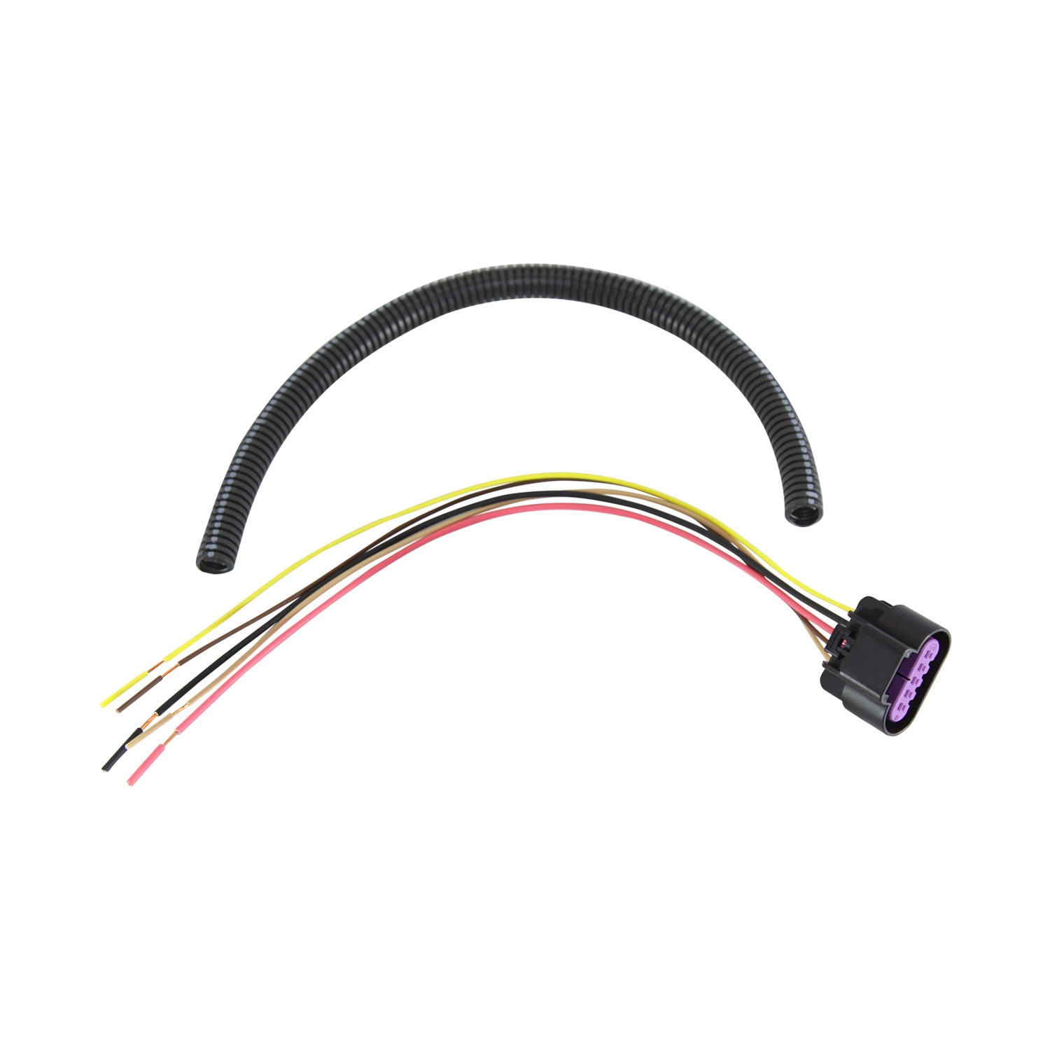
Mass Air Flow Sensor Pigtail Harness PGTL 003 Wiring Splices Pigtails Racetronix
The image title is Mass Air Flow Sensor Pigtail Harness PGTL 003 Wiring Splices Pigtails Racetronix, features dimensions of width 1500 px and height 1500 px, with a file size of 1500 x 1500. This image image/jpeg type visual are source from www.racetronix.biz
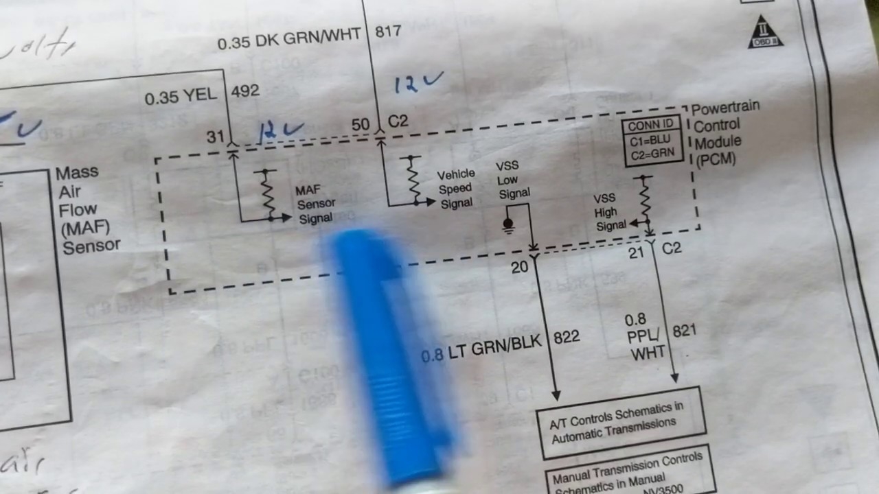
MAF MASS AIR FLOW SENSOR ELECTRICAL CONNECTIONS THEORY AND TROUBLESHOOTING FROM WIRING DIAGRAM YouTube
The image title is MAF MASS AIR FLOW SENSOR ELECTRICAL CONNECTIONS THEORY AND TROUBLESHOOTING FROM WIRING DIAGRAM YouTube, features dimensions of width 1280 px and height 720 px, with a file size of 1280 x 720. This image image/jpeg type visual are source from m.youtube.com.
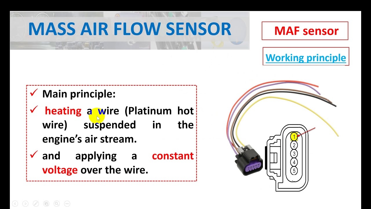
Mass Air Flow Sensor Hot Wire Symptoms Of A Bad MAF Sensor YouTube
The image title is Mass Air Flow Sensor Hot Wire Symptoms Of A Bad MAF Sensor YouTube, features dimensions of width 1280 px and height 720 px, with a file size of 1280 x 720. This image image/jpeg type visual are source from m.youtube.com.
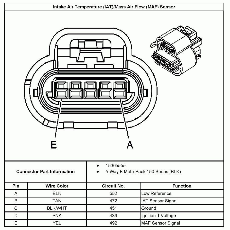
GM 5 Wire MAF Sensor Wiring Diagram JustAnswer Q A
The image title is GM 5 Wire MAF Sensor Wiring Diagram JustAnswer Q A, features dimensions of width 960 px and height 958 px, with a file size of 960 x 958.
The images on this page, sourced from Google for educational purposes, may be copyrighted. If you own an image and wish its removal or have copyright concerns, please contact us. We aim to promptly address these issues in compliance with our copyright policy and DMCA standards. Your cooperation is appreciated.
Related Keywords to Gm Mass Air Flow Sensor Wiring Diagram:
gm mass air flow sensor problems,gm mass air flow sensor specifications,gm mass air flow sensor wiring diagram,how to program a mass air flow sensor

