Table of Contents
Electrical Wiring Diagrams For Contactors
Electrical Wiring Diagrams For Contactors
When it comes to electrical systems, contactors play a crucial role in controlling the flow of electricity. These devices are used in various applications, from lighting control to motor starters. To ensure proper installation and troubleshooting, having accurate electrical wiring diagrams for contactors is essential. These diagrams provide a visual representation of the electrical connections, making it easier to understand how the system operates and how components are interconnected. Let’s delve into the world of electrical wiring diagrams for contactors and explore their significance in the realm of electrical engineering.
The Basics of Contactors
Before we dive into wiring diagrams, let’s first understand what contactors are and how they function. Contactors are electrical switches that are typically used to control large electrical loads. They consist of a coil that generates a magnetic field when energized, pulling contacts together to close the circuit. Contactors are commonly found in HVAC systems, industrial machinery, and automation applications where a high current needs to be controlled.
Key Components of a Contactor:
Coil: Generates a magnetic field to actuate the contacts.
Contacts: Conductors that open and close the circuit.
Auxiliary Contacts: Used for signaling or interlocking purposes.
Enclosure: Provides protection against environmental factors.
Importance of Electrical Wiring Diagrams
Electrical wiring diagrams for contactors serve as a blueprint for understanding the electrical connections within a system. These diagrams allow electricians and engineers to visualize the circuit layout, identify components, and troubleshoot any issues that may arise. By following a wiring diagram, professionals can ensure that the installation is done correctly, minimizing the risk of errors or malfunctions.
Benefits of Using Wiring Diagrams:
Clarity: Provides a clear representation of the electrical circuit.
Accuracy: Ensures proper connection of components.
Troubleshooting: Helps identify and resolve issues quickly.
Standardization: Promotes consistency in installations.
Types of Wiring Diagrams
There are various types of wiring diagrams used in the field of electrical engineering. For contactors, the most common types include line diagrams, ladder diagrams, and schematic diagrams. Each type serves a specific purpose and provides a unique perspective on the electrical system.
Line Diagrams:
Line diagrams are simple and intuitive, showing the physical layout of components and their connections. These diagrams are easy to follow and are often used for initial system design and layout planning.
Ladder Diagrams:
Ladder diagrams are widely used in industrial settings for programming and troubleshooting control systems. They represent the electrical circuit in a ladder-like format, with rungs depicting the various components and their interconnections.
Schematic Diagrams:
Schematic diagrams provide a detailed illustration of the electrical system, showing the relationship between components and their electrical characteristics. These diagrams are essential for in-depth analysis and advanced troubleshooting of complex systems.
Conclusion
In conclusion, electrical wiring diagrams for contactors are invaluable tools for understanding, installing, and troubleshooting electrical systems. By utilizing these diagrams, professionals can ensure the safe and efficient operation of contactors in various applications. Whether you are an electrician, engineer, or student in the field of electrical engineering, mastering the interpretation of wiring diagrams is essential for success in this dynamic industry.
Related to Electrical Wiring Diagrams For Contactors
- Electrical Wiring Diagram House
- Electrical Wiring Diagram Software
- Electrical Wiring Diagram Switch
- Electrical Wiring Diagram Symbols
- Electrical Wiring Diagrams
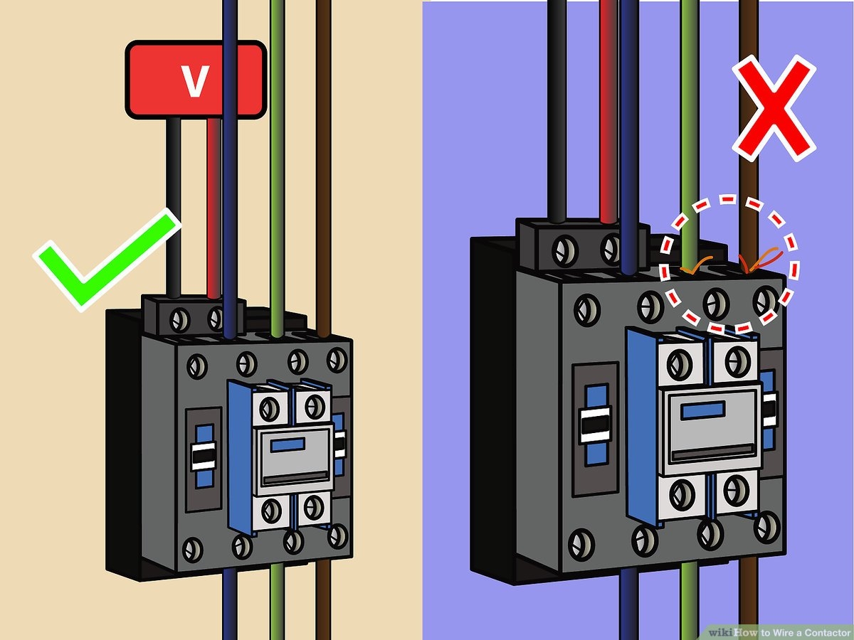
How To Wire A Contactor 8 Steps With Pictures WikiHow
The image title is How To Wire A Contactor 8 Steps With Pictures WikiHow, features dimensions of width 1200 px and height 900 px, with a file size of 1200 x 900 px. This image image/jpeg type visual are source from www.wikihow.com.
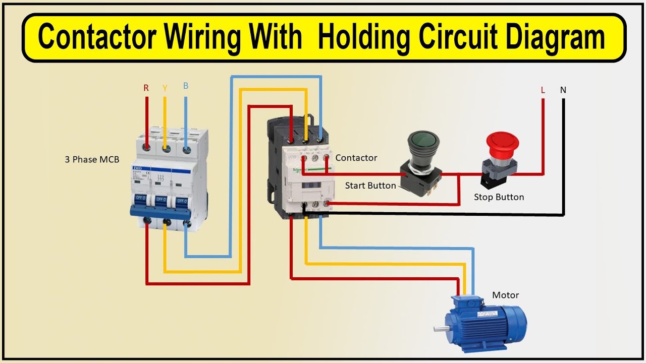
How To Make Contactor Wiring With Holding Circuit Diagram Contactor YouTube
The image title is How To Make Contactor Wiring With Holding Circuit Diagram Contactor YouTube, features dimensions of width 1280 px and height 720 px, with a file size of 1280 x 720 px. This image image/jpeg type visual are source from www.youtube.com.
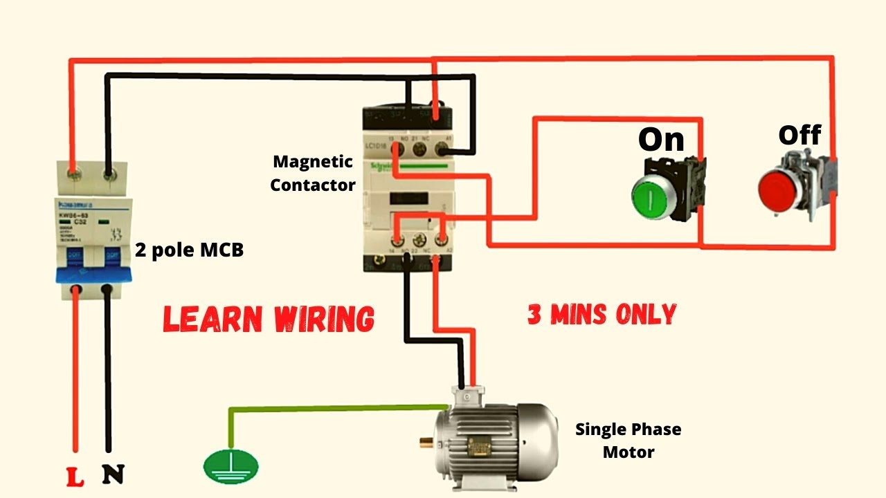
Single Phase Motor Connection With Magnetic Contactor Wiring Diagram YouTube
The image title is Single Phase Motor Connection With Magnetic Contactor Wiring Diagram YouTube, features dimensions of width 1280 px and height 720 px, with a file size of 1280 x 720. This image image/jpeg type visual are source from www.youtube.com.
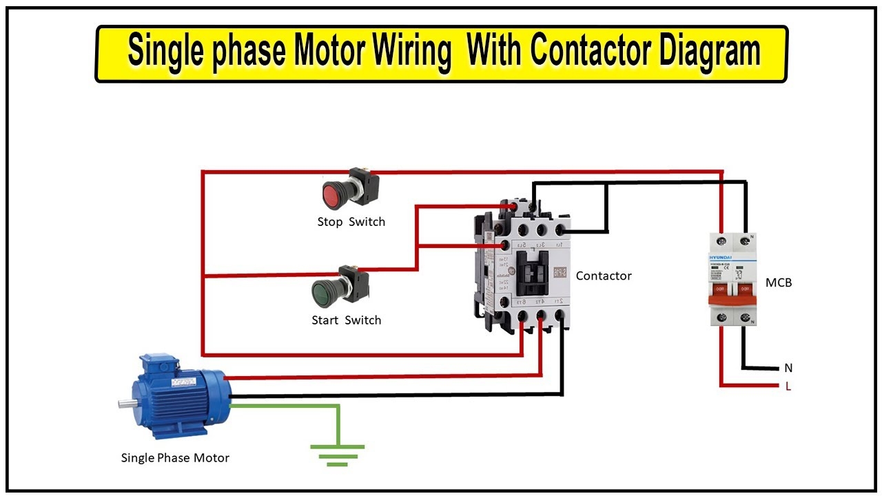
How To Make Single Phase Motor Wiring With Contactor Diagram Motor YouTube
The image title is How To Make Single Phase Motor Wiring With Contactor Diagram Motor YouTube, features dimensions of width 1280 px and height 720 px, with a file size of 1280 x 720. This image image/jpeg type visual are source from www.youtube.com.
Single Phase Motor Connection With Magnetic Contactor Wiring Diagram YouTube
The image title is Single Phase Motor Connection With Magnetic Contactor Wiring Diagram YouTube, features dimensions of width 1280 px and height 720 px, with a file size of 1280 x 720. This image image/jpeg type visual are source from www.youtube.com
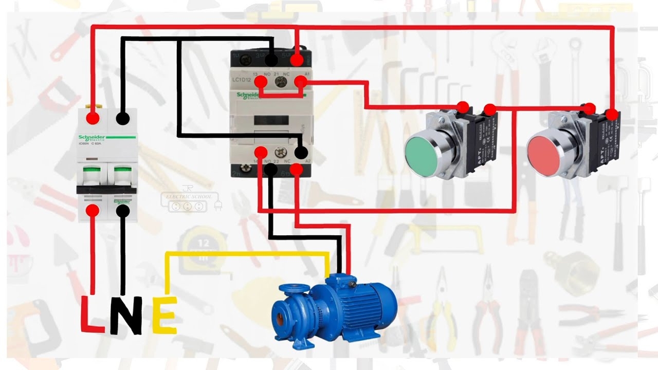
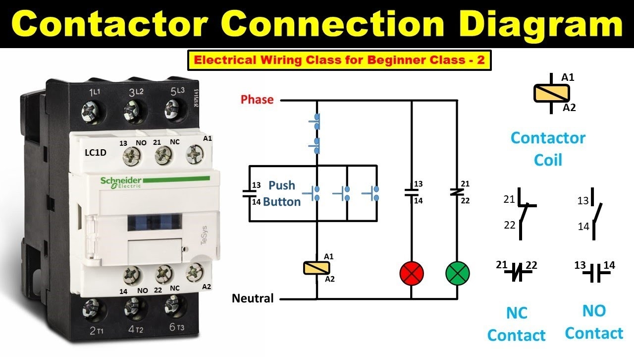
How To Do Contactor Wiring Electrical Wiring Class For Beginner Class 2 TheElectricalGuy YouTube
The image title is How To Do Contactor Wiring Electrical Wiring Class For Beginner Class 2 TheElectricalGuy YouTube, features dimensions of width 1280 px and height 720 px, with a file size of 1280 x 720. This image image/jpeg type visual are source from m.youtube.com.
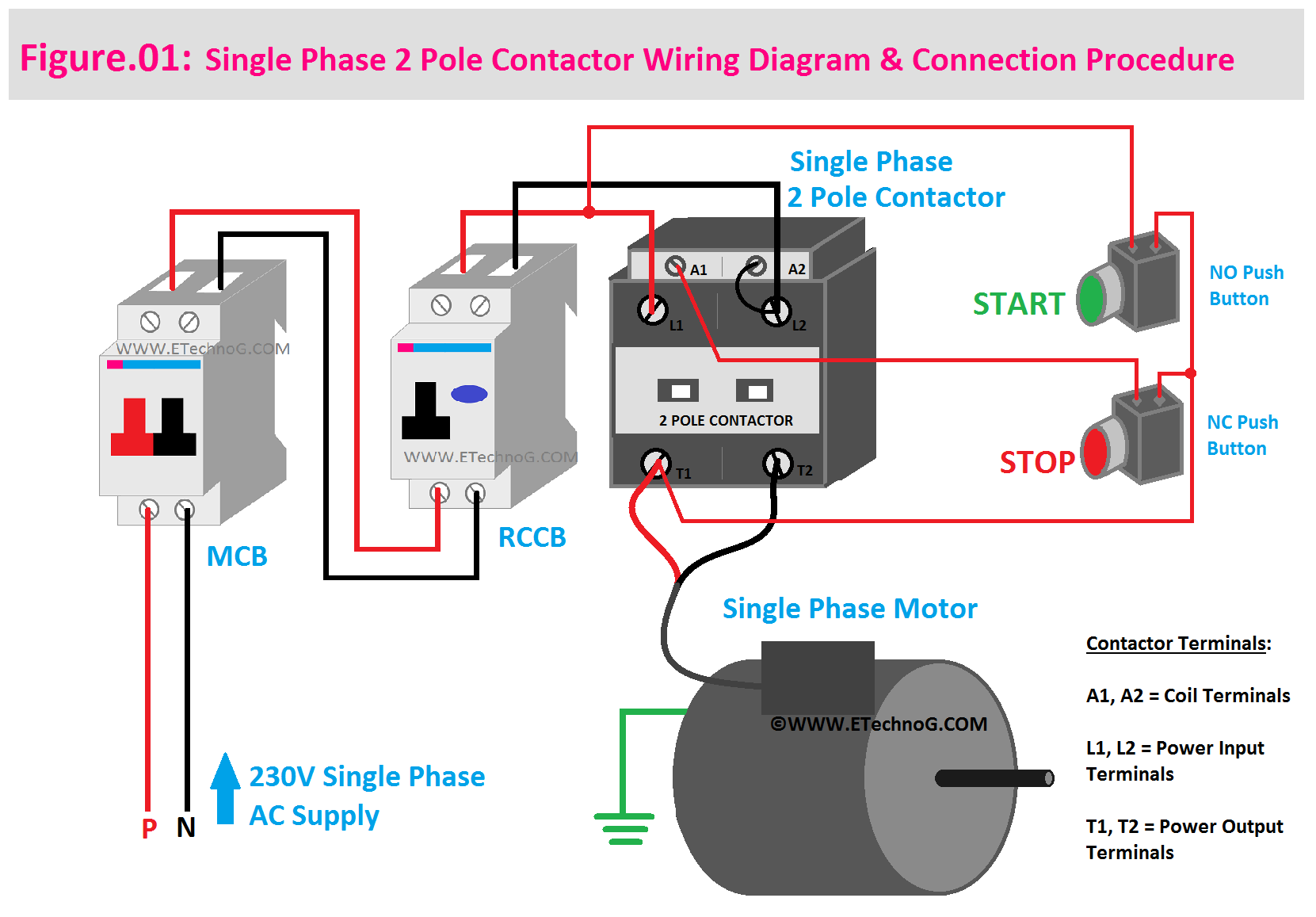
Single Phase 2 Pole Contactor Wiring Diagram Electrical Diagram Electrical Circuit Diagram Pole
The image title is Single Phase 2 Pole Contactor Wiring Diagram Electrical Diagram Electrical Circuit Diagram Pole, features dimensions of width 1661 px and height 1157 px, with a file size of 1661 x 1157. This image image/png type visual are source from www.pinterest.com.
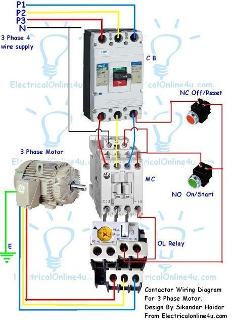
Contactor Wiring Guide For 3 Phase Motor With Circuit Breaker Overload Relay NC NO Switches Home Electrical Wiring Basic Electrical Wiring Electrical Wiring
The image title is Contactor Wiring Guide For 3 Phase Motor With Circuit Breaker Overload Relay NC NO Switches Home Electrical Wiring Basic Electrical Wiring Electrical Wiring, features dimensions of width 459 px and height 640 px, with a file size of 459 x 640.
The images on this page, sourced from Google for educational purposes, may be copyrighted. If you own an image and wish its removal or have copyright concerns, please contact us. We aim to promptly address these issues in compliance with our copyright policy and DMCA standards. Your cooperation is appreciated.
Related Keywords to Electrical Wiring Diagrams For Contactors:
