Table of Contents
The Ultimate Guide to Can Bus Wiring Diagram
The Value of Can Bus Wiring Diagram
In the realm of automotive technology, the Can Bus Wiring Diagram stands out as a crucial tool for understanding the intricate network of communication within a vehicle. From transmitting data between various components to ensuring seamless integration of electronic systems, the Can Bus Wiring Diagram serves as a blueprint for efficiency and reliability. By delving into the details of this diagram, one can unravel the complexities of modern automotive electronics and harness the power of interconnected systems.
Understanding Can Bus Wiring
The Controller Area Network (Can Bus) is a standardized communication protocol used in vehicles to enable microcontrollers and devices to communicate with each other without a host computer. This network relies on a two-wire system to transmit information between nodes, allowing for real-time data exchange and synchronization. The Can Bus Wiring Diagram illustrates the connections between these nodes, highlighting the pathways through which information flows within the vehicle’s electronic ecosystem.
Key Components of a Can Bus Wiring Diagram
When examining a Can Bus Wiring Diagram, it’s essential to identify the key components that make up this intricate network. These components include:
Nodes: Electronic control units that communicate with each other via the Can Bus.
Bus lines: Two wires (CAN-High and CAN-Low) that facilitate data transmission.
Terminators: Resistors at each end of the bus to prevent signal reflections.
Benefits of Can Bus Wiring Diagram
By utilizing a Can Bus Wiring Diagram, automotive technicians and enthusiasts can gain valuable insights into the functionality of a vehicle’s electronic systems. Some of the key benefits of this diagram include:
Diagnostic purposes: Easily pinpoint and troubleshoot communication issues between components.
Integration: Ensure seamless integration of new devices and systems into the existing network.
Efficiency: Streamline the design and development process of electronic systems within a vehicle.
Importance of Proper Wiring
Proper wiring is crucial to the success of a Can Bus system, as any discrepancies or faults in the wiring can disrupt communication between nodes. By adhering to the guidelines outlined in the Can Bus Wiring Diagram, individuals can ensure optimal performance and reliability of their vehicle’s electronic systems. It’s essential to follow industry standards and best practices when implementing Can Bus wiring to avoid potential issues down the road.
Conclusion
In conclusion, the Can Bus Wiring Diagram serves as a cornerstone in the world of automotive electronics, providing a roadmap for efficient communication and integration of electronic systems within a vehicle. By understanding the intricacies of this diagram and following proper wiring practices, individuals can harness the full potential of the Can Bus network and ensure seamless operation of their vehicles. Whether you’re a seasoned technician or a curious enthusiast, exploring the realm of Can Bus Wiring Diagram can unlock a world of possibilities in modern automotive technology.
Related to Can Bus Wiring Diagram
- Camper Electrical Wiring Diagram
- Camper Plug Wiring Diagram
- Camper Trailer Wiring Diagram
- Camper Wiring Diagram
- Campervan Wiring Diagram
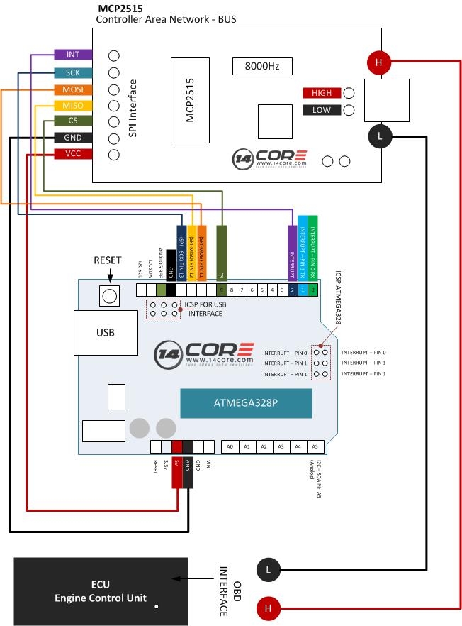
Wiring The MCP2515 Controller Area Network CAN BUS Diagnostics 14core
The image title is Wiring The MCP2515 Controller Area Network CAN BUS Diagnostics 14core, features dimensions of width 652 px and height 882 px, with a file size of 652 x 882 px. This image image/jpeg type visual are source from www.14core.com.
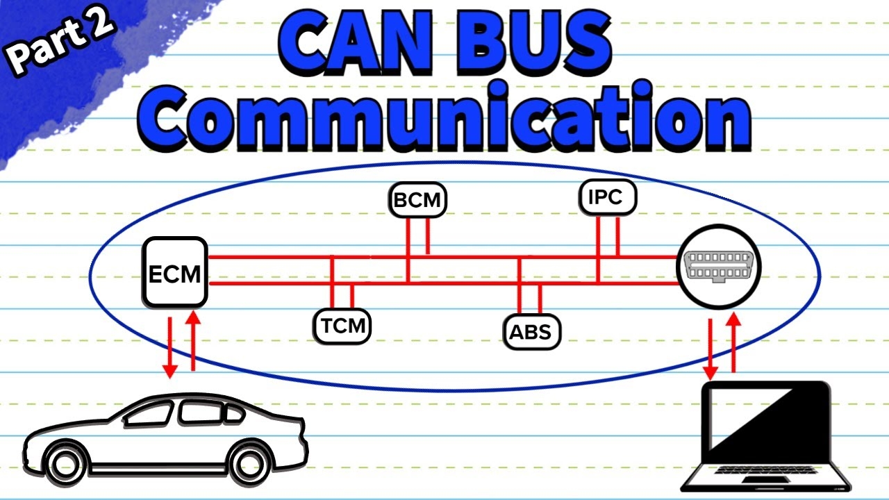
CAN Bus Wiring And Protocol Explained Part 2 YouTube
The image title is CAN Bus Wiring And Protocol Explained Part 2 YouTube, features dimensions of width 1280 px and height 720 px, with a file size of 1280 x 720 px. This image image/jpeg type visual are source from www.youtube.com.
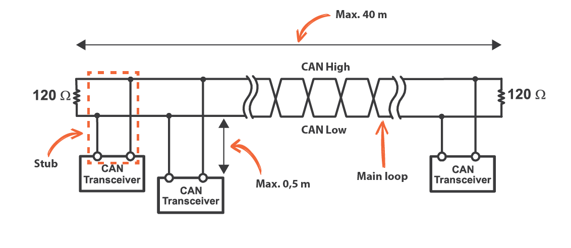
Practical Tips CAN Bus KMP Drivetrain Solutions
The image title is Practical Tips CAN Bus KMP Drivetrain Solutions, features dimensions of width 1132 px and height 492 px, with a file size of 1132 x 492. This image image/png type visual are source from www.kmpdrivetrain.com.
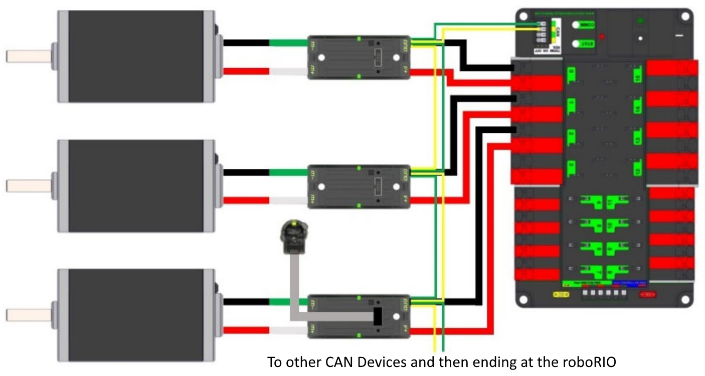
CAN Wiring Basics FIRST Robotics Competition Documentation
The image title is CAN Wiring Basics FIRST Robotics Competition Documentation, features dimensions of width 1406 px and height 750 px, with a file size of 1406 x 750. This image image/png type visual are source from docs.wpilib.org.
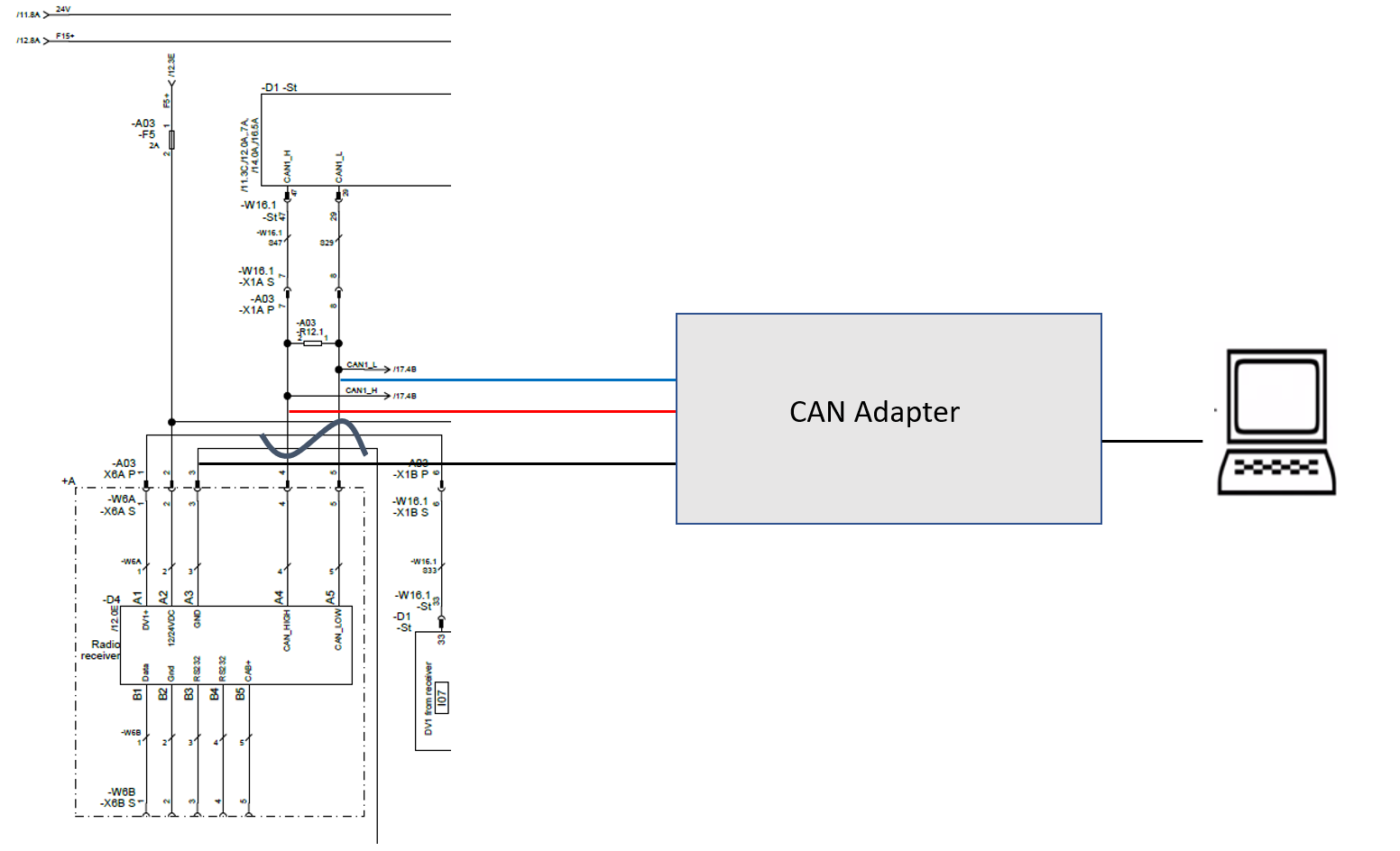
Microcontroller Is This CANbus Wiring Reasonable Electrical Engineering Stack Exchange
The image title is Microcontroller Is This CANbus Wiring Reasonable Electrical Engineering Stack Exchange, features dimensions of width 1552 px and height 944 px, with a file size of 1552 x 944. This image image/png type visual are source from electronics.stackexchange.com
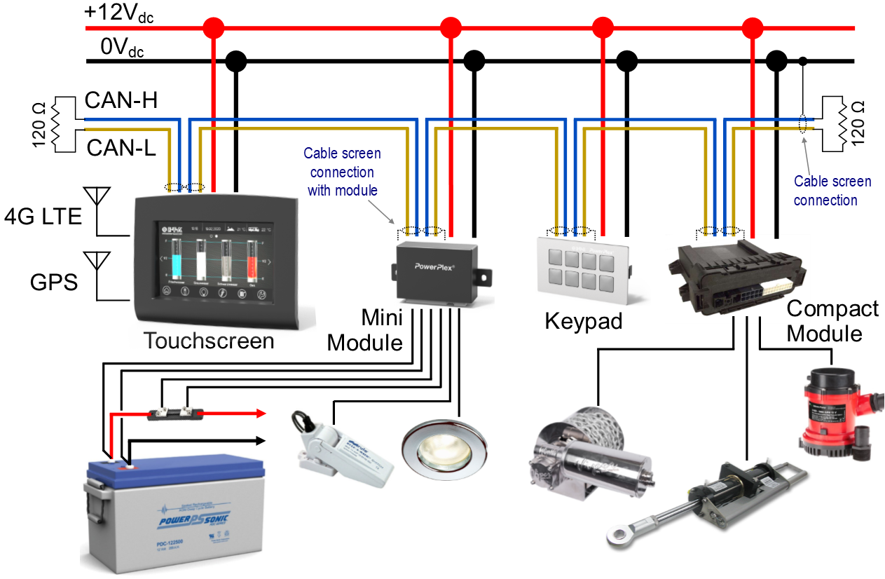
CAN Bus Networking Hazeltontechnologies
The image title is CAN Bus Networking Hazeltontechnologies, features dimensions of width 1263 px and height 826 px, with a file size of 1263 x 826. This image image/png type visual are source from www.hazeltontechnologies.com.
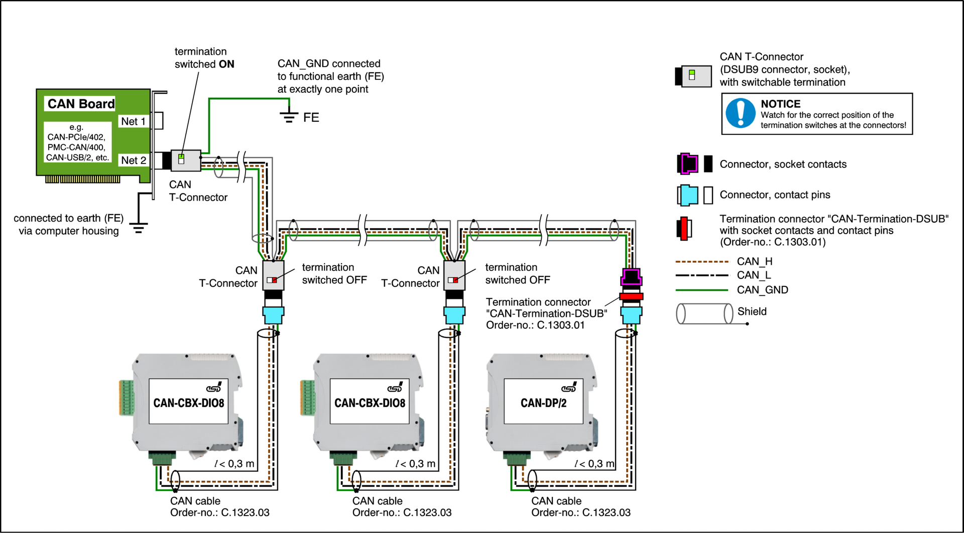
Professional Wiring Of Galvanically Isolated CAN Networks
The image title is Professional Wiring Of Galvanically Isolated CAN Networks, features dimensions of width 1920 px and height 1063 px, with a file size of 1920 x 1063. This image image/png type visual are source from esd.eu.
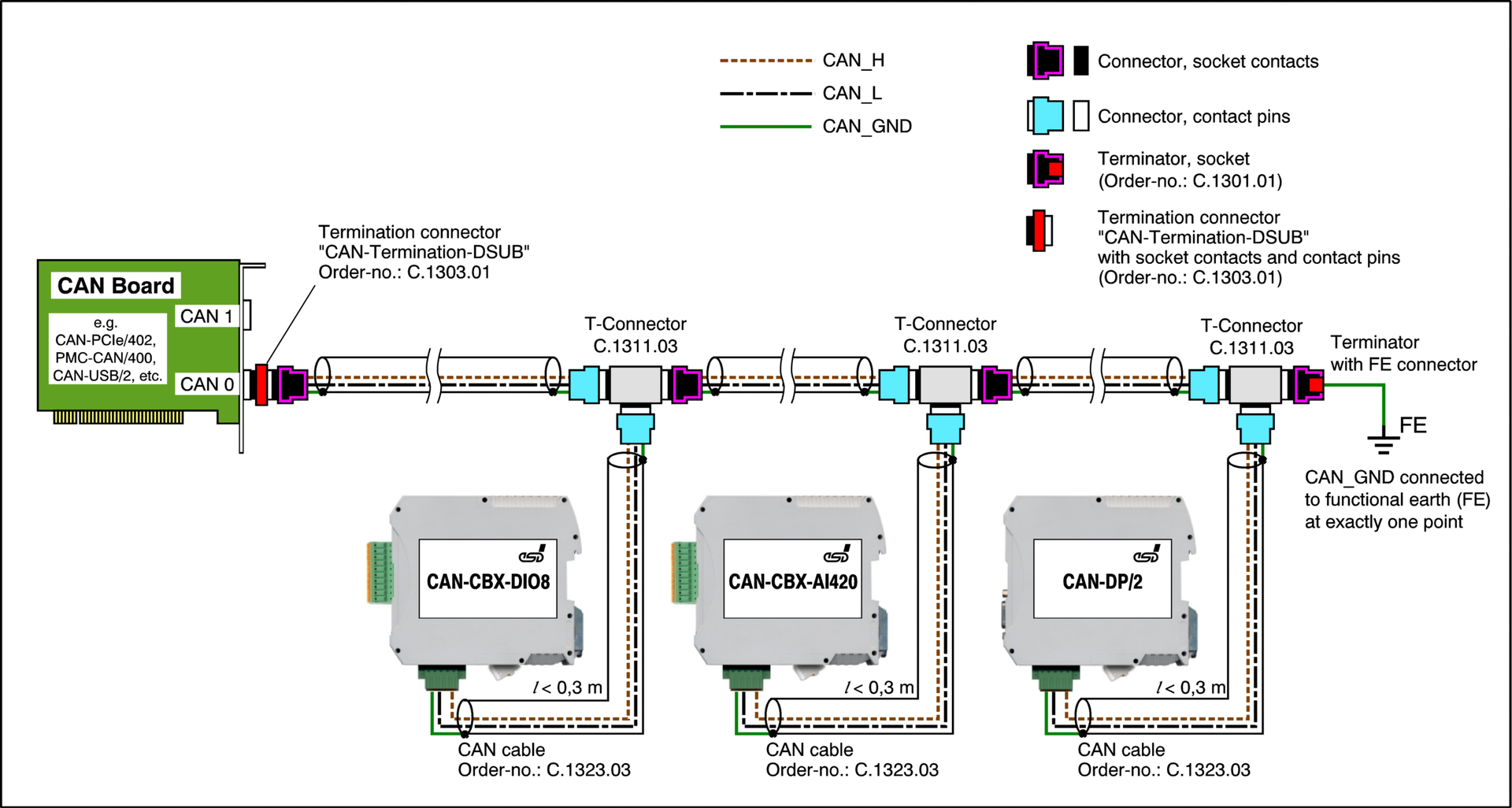
Professional Wiring Of Galvanically Isolated CAN Networks
The image title is Professional Wiring Of Galvanically Isolated CAN Networks, features dimensions of width 1920 px and height 1026 px, with a file size of 1920 x 1026.
The images on this page, sourced from Google for educational purposes, may be copyrighted. If you own an image and wish its removal or have copyright concerns, please contact us. We aim to promptly address these issues in compliance with our copyright policy and DMCA standards. Your cooperation is appreciated.
Related Keywords to Can Bus Wiring Diagram:
can bus cable diagram,can bus system diagram,can bus wiring diagram,can bus wiring diagram pdf,can bus wiring diagram symbols
