Table of Contents
The Value of Boat Tachometer Wiring Diagram
When it comes to maintaining and troubleshooting your boat’s electrical system, having a comprehensive understanding of the wiring diagram is crucial. The boat tachometer wiring diagram serves as a roadmap for connecting the various electrical components of your vessel, ensuring smooth operation and accurate readings. By following the wiring diagram meticulously, you can avoid potential issues and ensure that your boat’s tachometer functions optimally. Let’s delve into the intricacies of boat tachometer wiring and explore how this diagram can be a valuable tool for boat owners.
Understanding Boat Tachometer Wiring
Components Involved in Boat Tachometer Wiring
The boat tachometer wiring diagram typically includes components such as the tachometer itself, the ignition switch, the pulse signal generator, and the power source. Each component plays a crucial role in ensuring that the tachometer accurately measures the engine’s RPM (revolutions per minute), providing vital information to the boat operator. Understanding how these components are interconnected is essential for troubleshooting any wiring issues that may arise.
Importance of Proper Wiring Connection
Proper wiring connection is paramount when it comes to boat tachometer installation. Any loose connections or incorrect wiring can result in inaccurate readings or even damage to the tachometer. The wiring diagram serves as a guide to help you identify the correct terminals for each component and ensure that the connections are secure. By adhering to the diagram, you can prevent potential electrical malfunctions and maintain the reliability of your tachometer.
Steps for Wiring a Boat Tachometer
Begin by locating the ignition switch on your boat and identifying the tachometer signal terminal.
Consult the boat tachometer wiring diagram to determine the correct wires that need to be connected.
Connect the power wire from the tachometer to the positive terminal of the power source.
Attach the ground wire from the tachometer to the negative terminal of the power source.
Connect the signal wire from the tachometer to the pulse signal generator.
Verify all connections are secure and test the tachometer to ensure it is functioning correctly.
Conclusion
In conclusion, the boat tachometer wiring diagram is a valuable resource for boat owners looking to install or troubleshoot their tachometer. By understanding the components involved, the importance of proper wiring connection, and following the steps outlined in the diagram, you can ensure that your boat’s tachometer operates smoothly and accurately. Whether you are a seasoned boat enthusiast or a novice in the world of marine electronics, mastering the art of boat tachometer wiring can enhance your boating experience and keep your vessel running at peak performance.
Related to Boat Tachometer Wiring Diagram
- Boat Ignition Switch Wiring Diagram
- Boat Kill Switch Wiring Diagram
- Boat Lift Switch Wiring Diagram
- Boat Marine Dual Battery Switch Wiring Diagram
- Boat Switch Panel Wiring Diagram
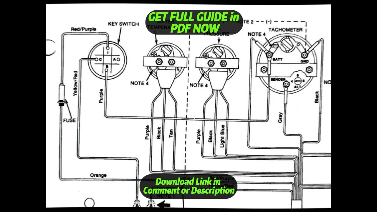
DIAGRAM Faria Gauges Wiring Diagram YouTube
The image title is DIAGRAM Faria Gauges Wiring Diagram YouTube, features dimensions of width 1280 px and height 720 px, with a file size of 1280 x 720 px. This image image/jpeg type visual are source from www.youtube.com.
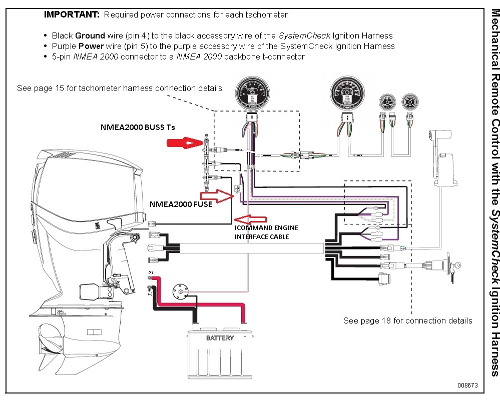
No Tach Or I Command Output Barnacle Bill S Marine Supply
The image title is No Tach Or I Command Output Barnacle Bill S Marine Supply, features dimensions of width 999 px and height 800 px, with a file size of 999 x 800 px. This image image/jpeg type visual are source from www.etecownersgroup.com.
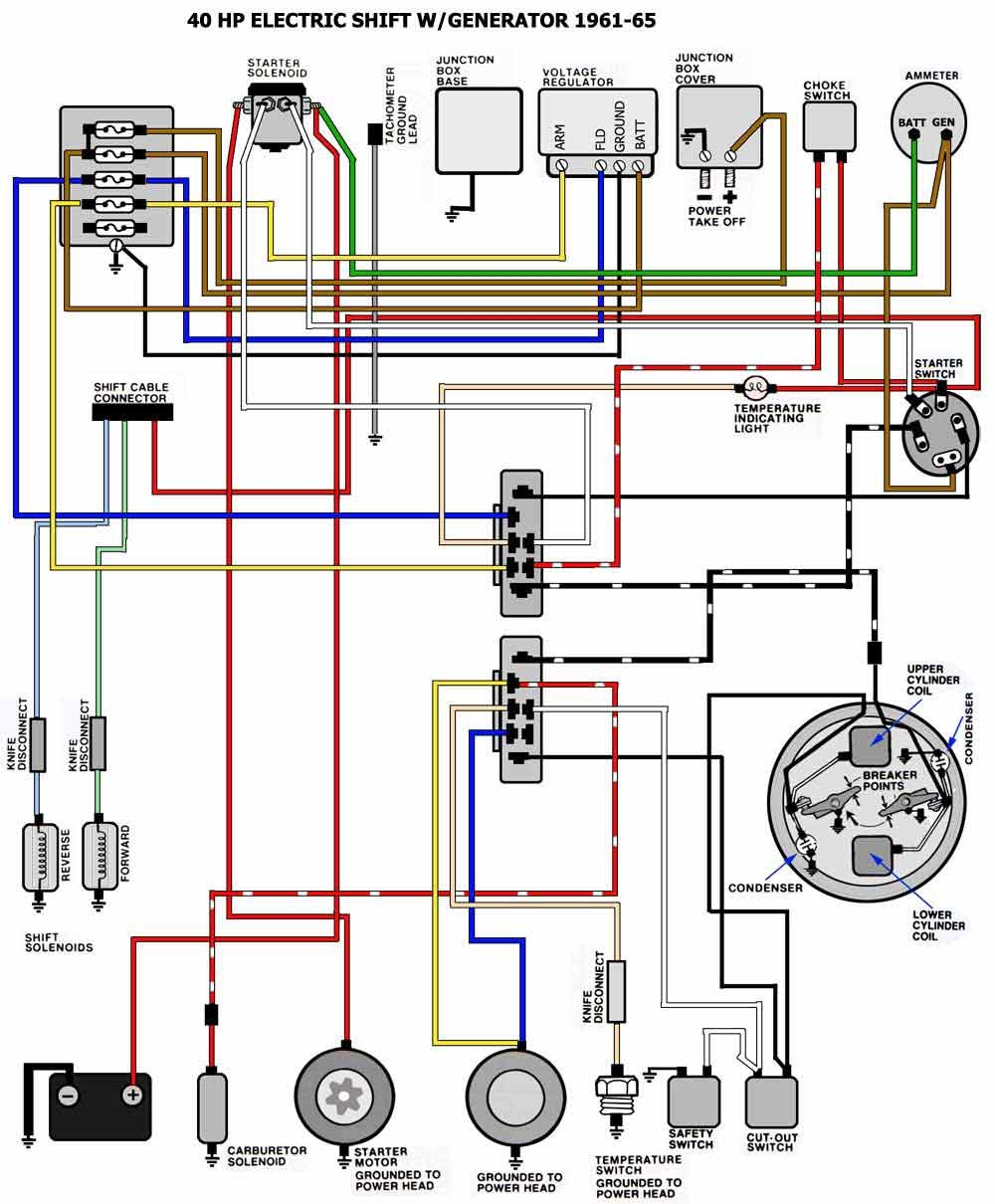
FiberGlassics Tach Signal Wire 64 Lark VI FiberGlassics Forums
The image title is FiberGlassics Tach Signal Wire 64 Lark VI FiberGlassics Forums, features dimensions of width 1000 px and height 1210 px, with a file size of 1000 x 1210. This image image/jpeg type visual are source from www.fiberglassics.com.
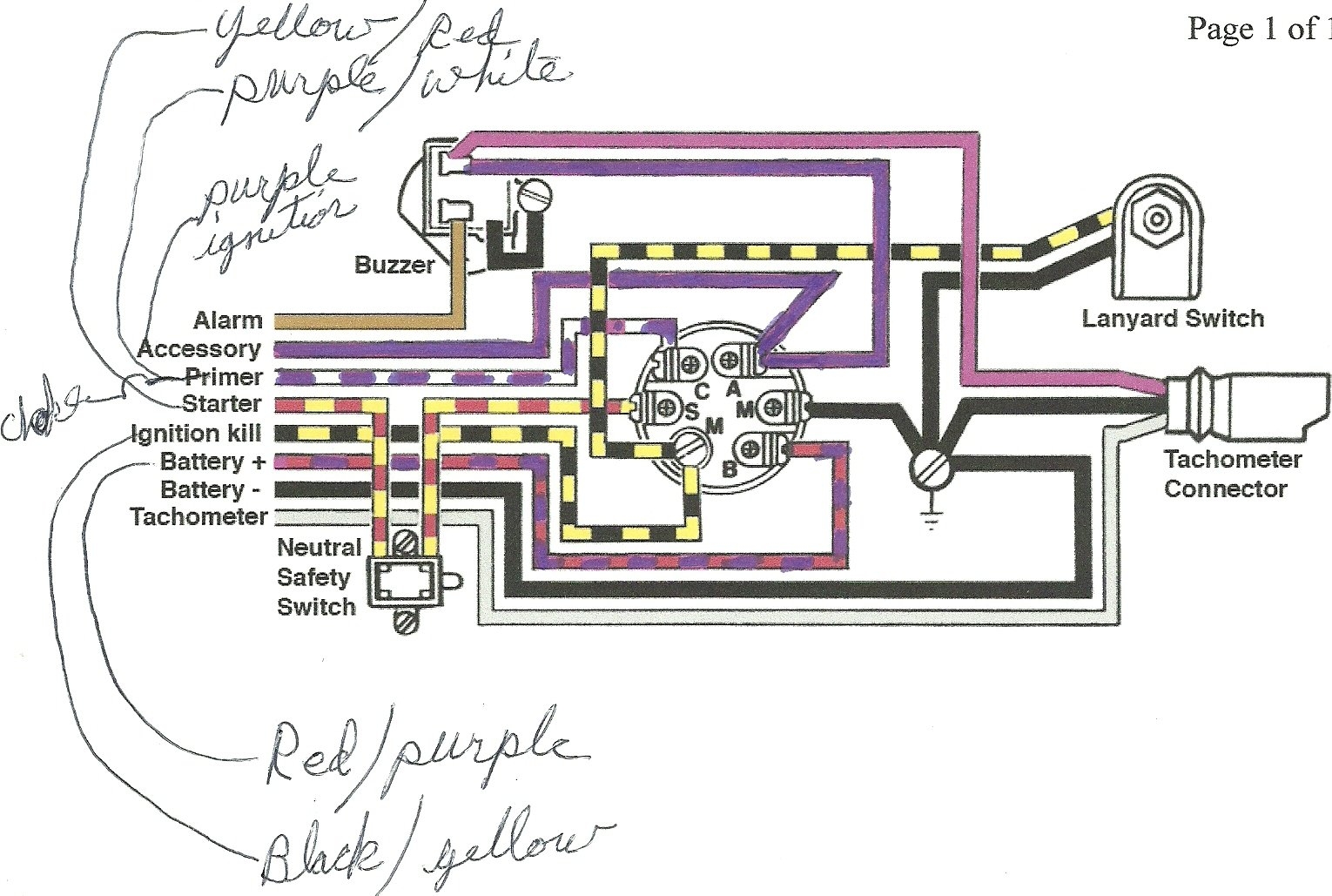
Please Help Installing Tachometer
The image title is Please Help Installing Tachometer, features dimensions of width 1530 px and height 1029 px, with a file size of 1530 x 1029. This image image/jpeg type visual are source from www.bbcboards.net.
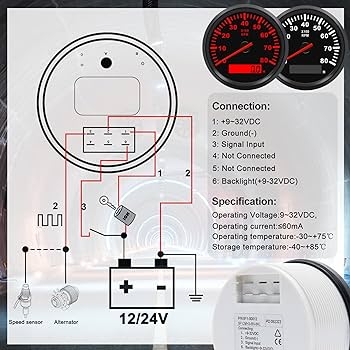
Amazon Geloo 85MM Boat RPM Tachometer Gauge Waterproof Outboard Tachometer Gauge 0 8000RPM Tacho Meter For Car Truck Marine Diesel Gasoline Engine RPM Tacho Gauge 9 32V With LCD Hourmeter Red Backlight Automotive
The image title is Amazon Geloo 85MM Boat RPM Tachometer Gauge Waterproof Outboard Tachometer Gauge 0 8000RPM Tacho Meter For Car Truck Marine Diesel Gasoline Engine RPM Tacho Gauge 9 32V With LCD Hourmeter Red Backlight Automotive, features dimensions of width 350 px and height 350 px, with a file size of 350 x 350. This image image/jpeg type visual are source from www.amazon.com
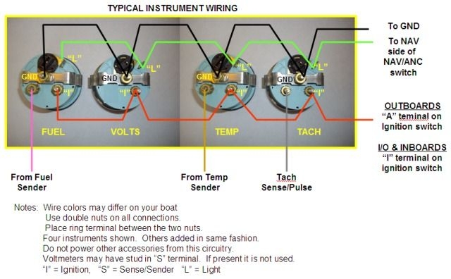
Trouble With Gauges Wiring Page 1 Iboats Boating Forums 557669 Boat Wiring Electric Boat Boat
The image title is Trouble With Gauges Wiring Page 1 Iboats Boating Forums 557669 Boat Wiring Electric Boat Boat, features dimensions of width 640 px and height 396 px, with a file size of 640 x 396. This image image/jpeg type visual are source from ar.pinterest.com.
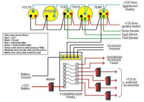
Outboard Boat Gauge DiagraM Google Search Boat Wiring Electric Boat Outboard Boats
The image title is Outboard Boat Gauge DiagraM Google Search Boat Wiring Electric Boat Outboard Boats, features dimensions of width 612 px and height 432 px, with a file size of 612 x 432. This image image/jpeg type visual are source from ar.pinterest.com.
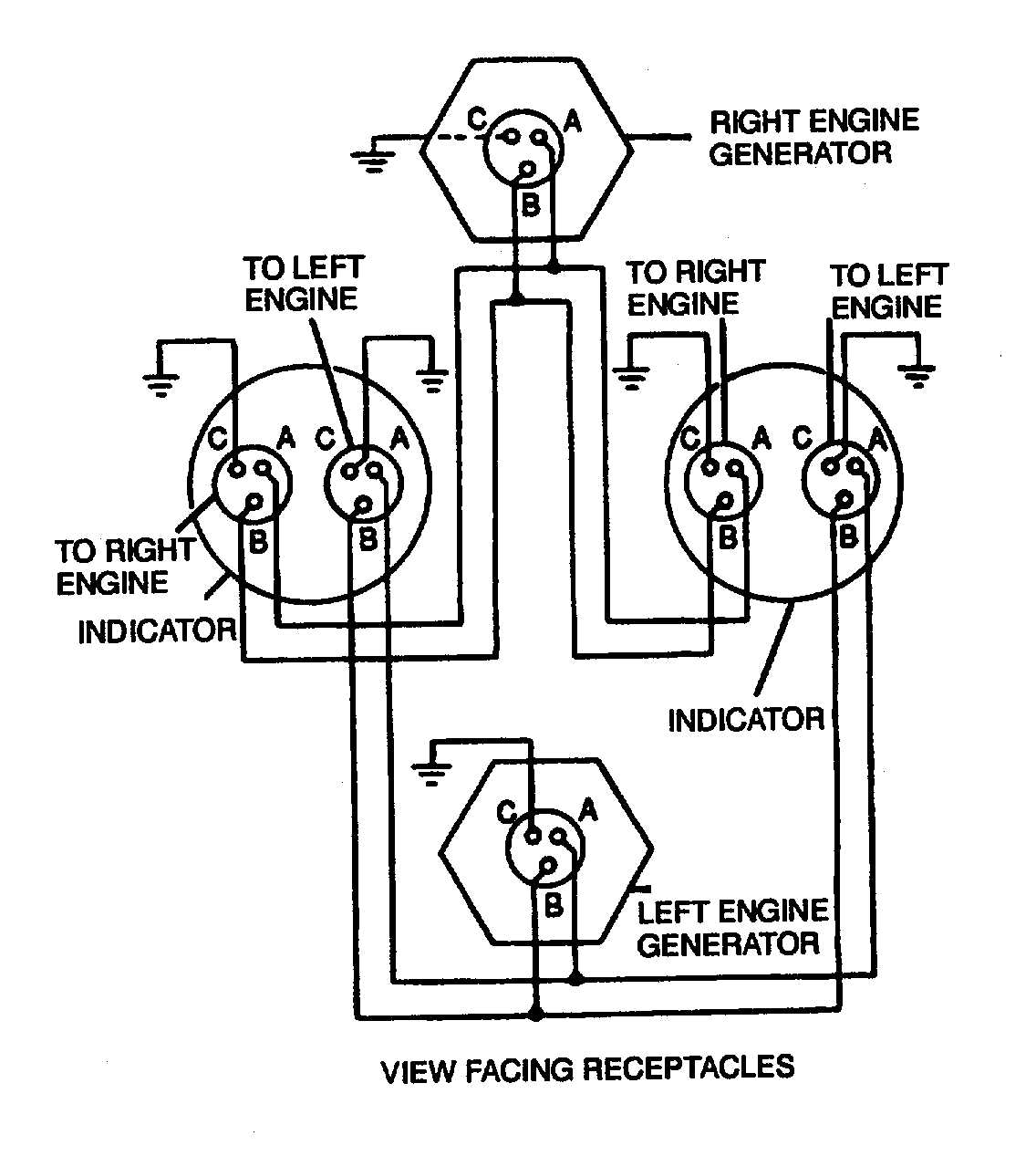
Figure 4 17 Dual Synchronous Rotor Tachometer Wiring Diagram
The image title is Figure 4 17 Dual Synchronous Rotor Tachometer Wiring Diagram, features dimensions of width 1136 px and height 1267 px, with a file size of 1136 x 1267.
The images on this page, sourced from Google for educational purposes, may be copyrighted. If you own an image and wish its removal or have copyright concerns, please contact us. We aim to promptly address these issues in compliance with our copyright policy and DMCA standards. Your cooperation is appreciated.
Related Keywords to Boat Tachometer Wiring Diagram:
boat gauges wiring diagram,boat speedometer wiring diagram,boat tach wiring diagram,boat tachometer wiring diagram,outboard tachometer wiring diagram
