Table of Contents
Exploring the Intricacies of Autometer Tachometer Wiring Diagram
Exploring the Intricacies of Autometer Tachometer Wiring Diagram
When it comes to the world of automotive performance, precision is key. Every enthusiast knows the importance of monitoring engine RPM to ensure optimal performance and safeguard against potential issues. At the heart of this monitoring process lies the Autometer tachometer, a trusted tool that provides real-time data on engine speed. However, the true magic happens when you delve into the realm of Autometer tachometer wiring diagram. This invaluable resource serves as a roadmap for connecting and configuring your tachometer, unlocking its full potential and ensuring seamless integration with your vehicle’s electrical system.
The Basics of Autometer Tachometer Wiring
Before embarking on the journey of wiring your Autometer tachometer, it’s essential to familiarize yourself with the basic components and principles involved. The wiring diagram acts as your guide, detailing the connections required to ensure accurate and reliable data transmission between the tachometer and your vehicle’s engine. Whether you’re a seasoned mechanic or a novice enthusiast, understanding the fundamentals of tachometer wiring is crucial for a successful installation.
Key Components
Tachometer: The central piece of the puzzle, responsible for measuring engine RPM.
Power Source: Provides the necessary voltage for the tachometer to function.
Ground Connection: Ensures a stable electrical pathway for accurate readings.
Signal Wire: Transmits data from the engine’s ignition system to the tachometer.
Wiring Process
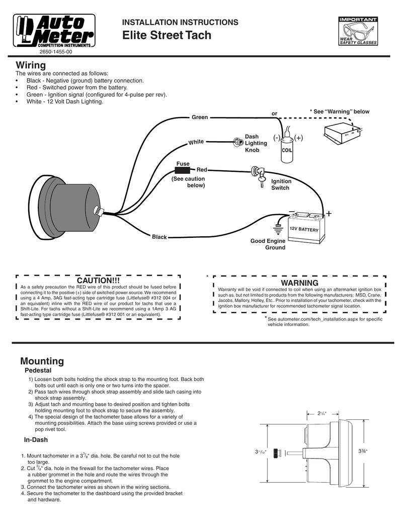
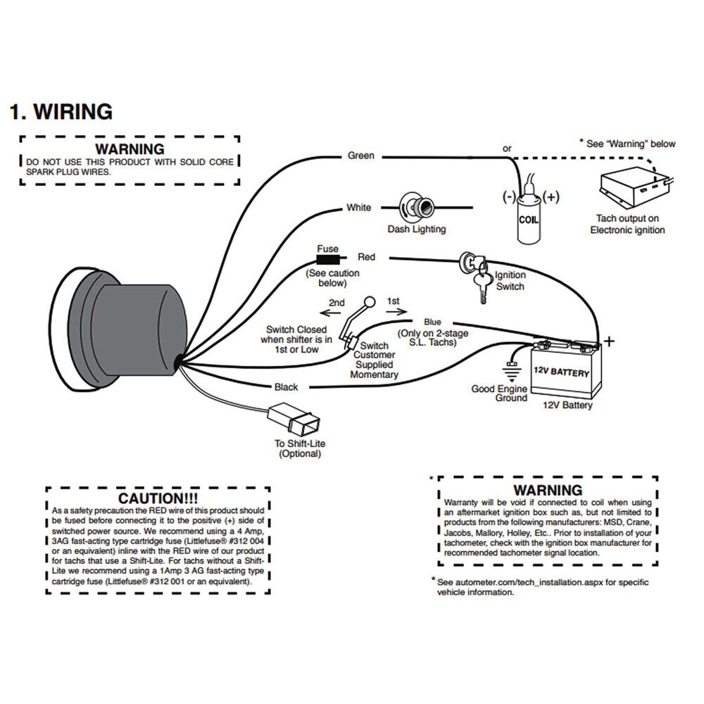
Identify the appropriate power source and ground connection points within your vehicle.
Connect the power wire from the tachometer to the designated power source.
Attach the ground wire to a suitable grounding point on the vehicle’s chassis.
Locate the signal wire and connect it to the tachometer according to the wiring diagram.
Test the tachometer to ensure proper functionality before finalizing the installation.
Advanced Wiring Configurations
Beyond the basic wiring setup, Autometer tachometer wiring diagrams can also accommodate advanced configurations for specialized applications. From multi-cylinder engines to aftermarket ignitions, these diagrams provide detailed instructions for adapting your tachometer to meet specific requirements. By following the guidelines outlined in the diagram, you can customize your tachometer setup to suit your unique needs and optimize performance.
Multi-Cylinder Support
For vehicles with multiple cylinders, the tachometer wiring diagram offers insights into configuring the tachometer to accurately display RPM data for each cylinder. By following the prescribed wiring connections, you can ensure that your tachometer provides precise readings across all cylinders, enabling you to fine-tune your engine’s performance with confidence.
Aftermarket Ignition Integration
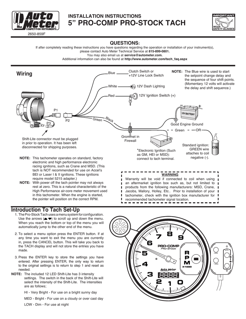
Integrating an aftermarket ignition system with your tachometer requires careful attention to detail. The wiring diagram serves as a crucial tool for establishing the necessary connections between the ignition module and the tachometer, ensuring seamless communication and accurate data transmission. With the guidance provided in the diagram, you can effortlessly synchronize your aftermarket ignition with your tachometer, unlocking a new level of performance monitoring and control.
Conclusion
In the world of automotive performance, knowledge is power, and Autometer tachometer wiring diagrams are the key to unlocking that power. By understanding the intricacies of tachometer wiring and harnessing the insights provided in the diagram, you can elevate your vehicle’s performance monitoring capabilities to new heights. Whether you’re a seasoned enthusiast or a novice mechanic, the guidance offered by Autometer tachometer wiring diagrams empowers you to take control of your engine’s RPM with confidence and precision.
Related to Autometer Tachometer Wiring Diagram
- Auto Wiring Diagram Symbols
- Auto Wiring Diagrams Free
- Automatic 3 Wire Bilge Pump Wiring Diagram
- Automatic Transfer Switch Wiring Diagram
- Autometer Tach Wiring Diagram
Elite Street Tach Wiring INSTALLATION INSTRUCTIONS Manualzz
The image title is Elite Street Tach Wiring INSTALLATION INSTRUCTIONS Manualzz, features dimensions of width 791 px and height 1024 px, with a file size of 791 x 1024 px. This image image/png type visual are source from manualzz.com.
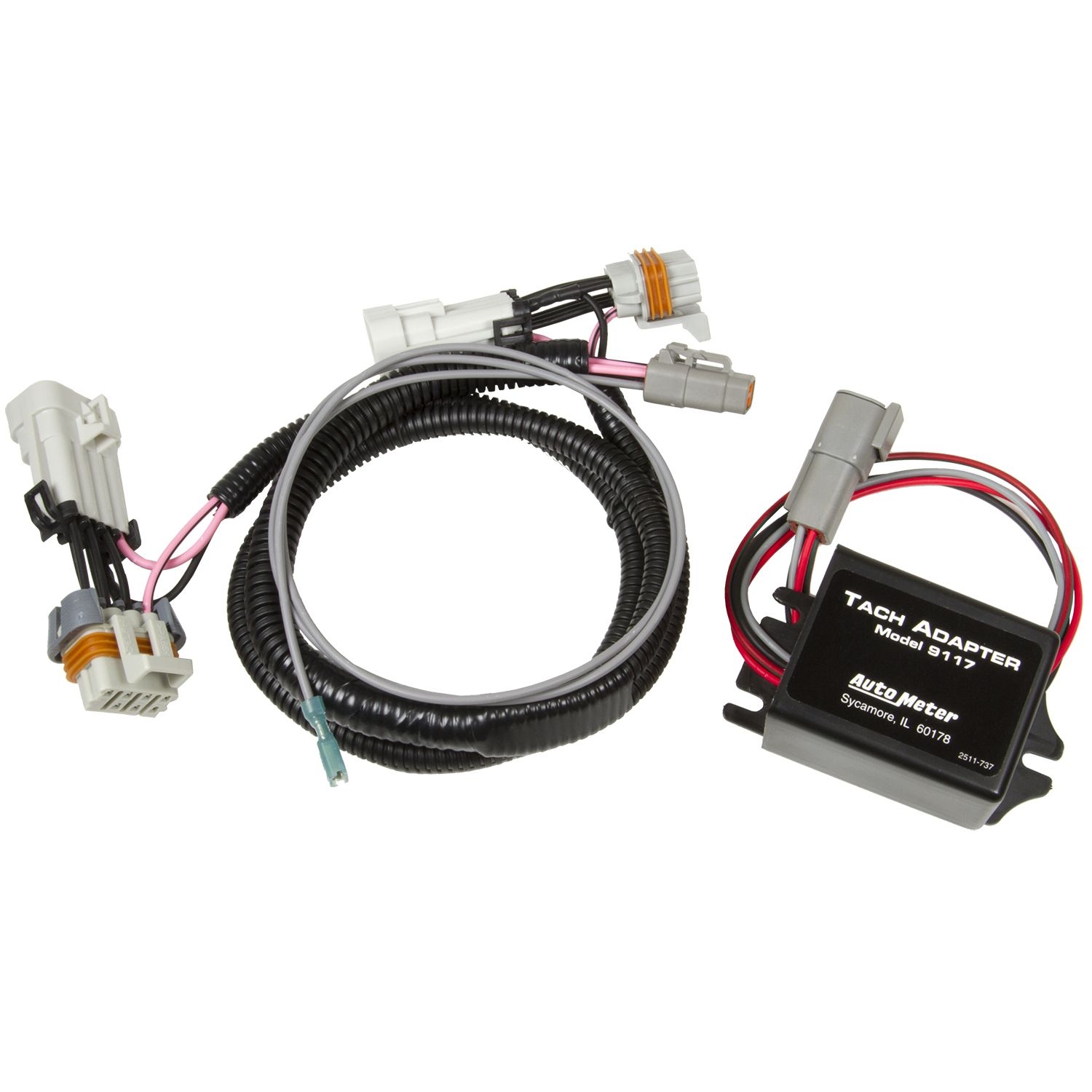
RPM SIGNAL ADAPTER FOR LS ENGINES INCL PLUG PLAY HARNESS
The image title is RPM SIGNAL ADAPTER FOR LS ENGINES INCL PLUG PLAY HARNESS, features dimensions of width 1500 px and height 1500 px, with a file size of 1500 x 1500 px. This image image/jpeg type visual are source from www.autometer.com.
Aftermarket Tach For A KA24DE 510 1600 Ratsun Forums
The image title is Aftermarket Tach For A KA24DE 510 1600 Ratsun Forums, features dimensions of width 1200 px and height 766 px, with a file size of 1200 x 766. This image image/png type visual are source from ratsun.net.
6601 AutoMeter Memory Tachometer Pro Comp 3 3 4 0 10000 Rpm Pedestal Jr Drag Renzi Ceramiche
The image title is 6601 AutoMeter Memory Tachometer Pro Comp 3 3 4 0 10000 Rpm Pedestal Jr Drag Renzi Ceramiche, features dimensions of width 1086 px and height 1600 px, with a file size of 1086 x 1600. This image image/jpeg type visual are source from www.renziceramiche.it.
Auto Meter Pro Stock Playback Tachometers Owner Manual Manualzz
The image title is Auto Meter Pro Stock Playback Tachometers Owner Manual Manualzz, features dimensions of width 791 px and height 1024 px, with a file size of 791 x 1024. This image image/png type visual are source from manualzz.com
Autometer AU3910 Sport Comp Silver Tachometer 5 With Adjustable Redline Pointer EBay
The image title is Autometer AU3910 Sport Comp Silver Tachometer 5 With Adjustable Redline Pointer EBay, features dimensions of width 1000 px and height 1000 px, with a file size of 1000 x 1000. This image image/jpeg type visual are source from www.ebay.com.
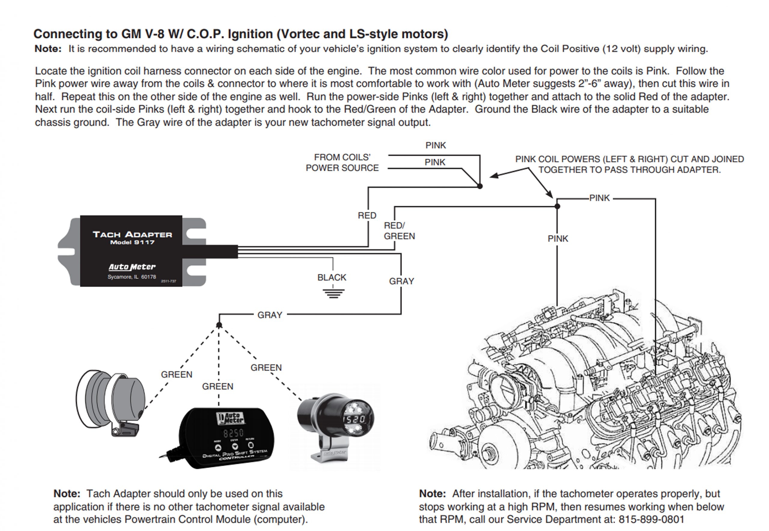
Ask Away With Jeff Smith Getting An Aftermarket Tach To Work In An LS Swapped 1969 Chevy Nova
The image title is Ask Away With Jeff Smith Getting An Aftermarket Tach To Work In An LS Swapped 1969 Chevy Nova, features dimensions of width 2560 px and height 1769 px, with a file size of 2560 x 1769. This image image/jpeg type visual are source from www.onallcylinders.com.
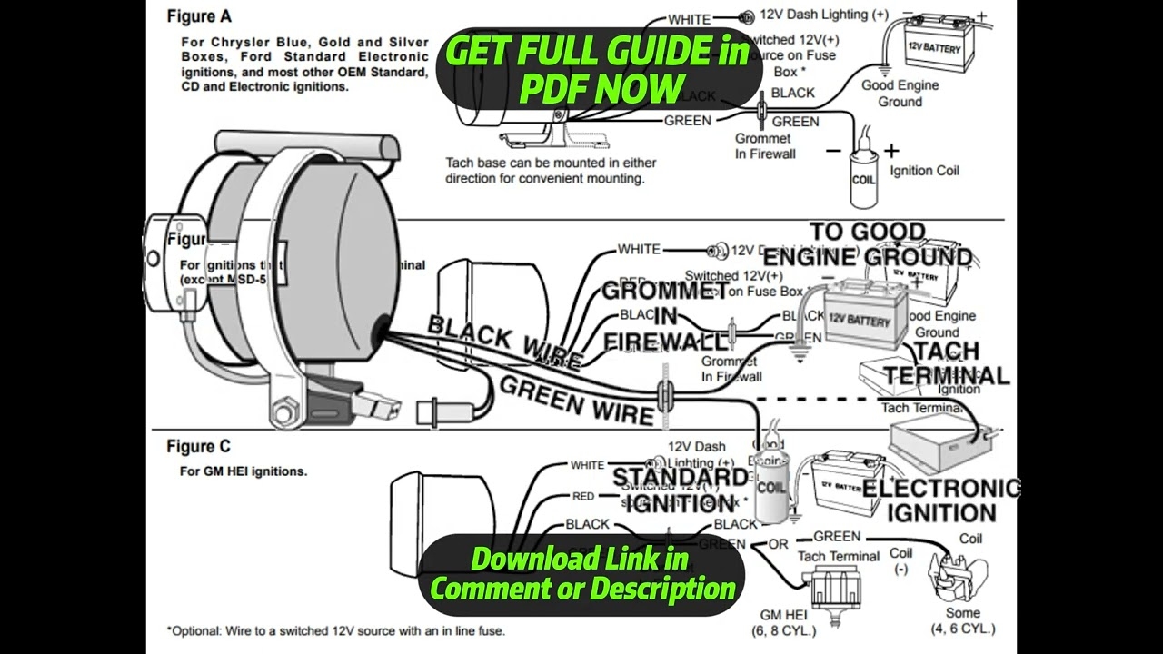
DIAGRAM Autometer Tach Wiring Diagram YouTube
The image title is DIAGRAM Autometer Tach Wiring Diagram YouTube, features dimensions of width 1280 px and height 720 px, with a file size of 1280 x 720.
The images on this page, sourced from Google for educational purposes, may be copyrighted. If you own an image and wish its removal or have copyright concerns, please contact us. We aim to promptly address these issues in compliance with our copyright policy and DMCA standards. Your cooperation is appreciated.
Related Keywords to Autometer Tachometer Wiring Diagram:
autometer gauges wiring diagram,autometer speedometer wiring diagram,autometer street tach wiring diagram,autometer tach wiring schematic,autometer tachometer wiring diagram
