Table of Contents
The Value of Ansul System Wiring Diagram
When it comes to fire protection systems in commercial kitchens, the Ansul System is a widely recognized name known for its reliability and efficiency. One crucial aspect of the Ansul System that ensures its proper functioning is the wiring diagram. The Ansul System wiring diagram serves as a blueprint for the electrical connections within the system, guiding installers and technicians on how to set up, maintain, and troubleshoot the system effectively. Understanding the importance of the Ansul System wiring diagram is essential for ensuring the safety of the kitchen staff and the premises.
Understanding the Components
Before delving into the details of the wiring diagram, it’s essential to have a basic understanding of the components that make up the Ansul System. This includes the control panel, detection devices, agent storage tanks, nozzles, and discharge hoses. Each component plays a vital role in detecting and suppressing fires in the kitchen environment. The wiring diagram illustrates how these components are interconnected to form a cohesive fire suppression system.
Installation and Maintenance Guidelines
The Ansul System wiring diagram provides clear instructions on how to install and maintain the system properly. Whether you are setting up a new system or conducting routine maintenance, referring to the wiring diagram ensures that the electrical connections are made correctly and in compliance with safety standards. Additionally, the diagram outlines the testing procedures to verify the functionality of the system, allowing for timely troubleshooting and repairs when needed.
Troubleshooting and Repairs
In the event of a system malfunction or component failure, the Ansul System wiring diagram is a valuable resource for troubleshooting and making repairs. By following the wiring diagram, technicians can identify the root cause of the issue and take the necessary steps to rectify it promptly. This minimizes downtime and ensures that the fire suppression system is always ready to respond effectively in case of an emergency.
Compliance and Regulations
Adhering to industry regulations and safety standards is paramount when it comes to fire protection systems. The Ansul System wiring diagram serves as a reference for ensuring that the system meets the required specifications and guidelines set forth by regulatory bodies. By following the wiring diagram during installation and maintenance, you can demonstrate compliance with regulatory requirements and enhance the overall safety of the kitchen environment.
Conclusion
In conclusion, the Ansul System wiring diagram is a crucial tool for ensuring the proper functioning and safety of commercial kitchen fire protection systems. By understanding the components, following installation and maintenance guidelines, utilizing the diagram for troubleshooting and repairs, and ensuring compliance with regulations, you can effectively manage and maintain an Ansul System for optimal performance. Investing time in comprehending the value of the Ansul System wiring diagram pays off in the form of a reliable and efficient fire suppression system that protects lives and property.
Related to Ansul System Wiring Diagram
- Amp Gauge Wiring Diagram
- Amp Research Power Step Wiring Diagram
- Amp Wiring Diagram
- Amplifier Wiring Diagram
- Ansul Micro Switch Wiring Diagram
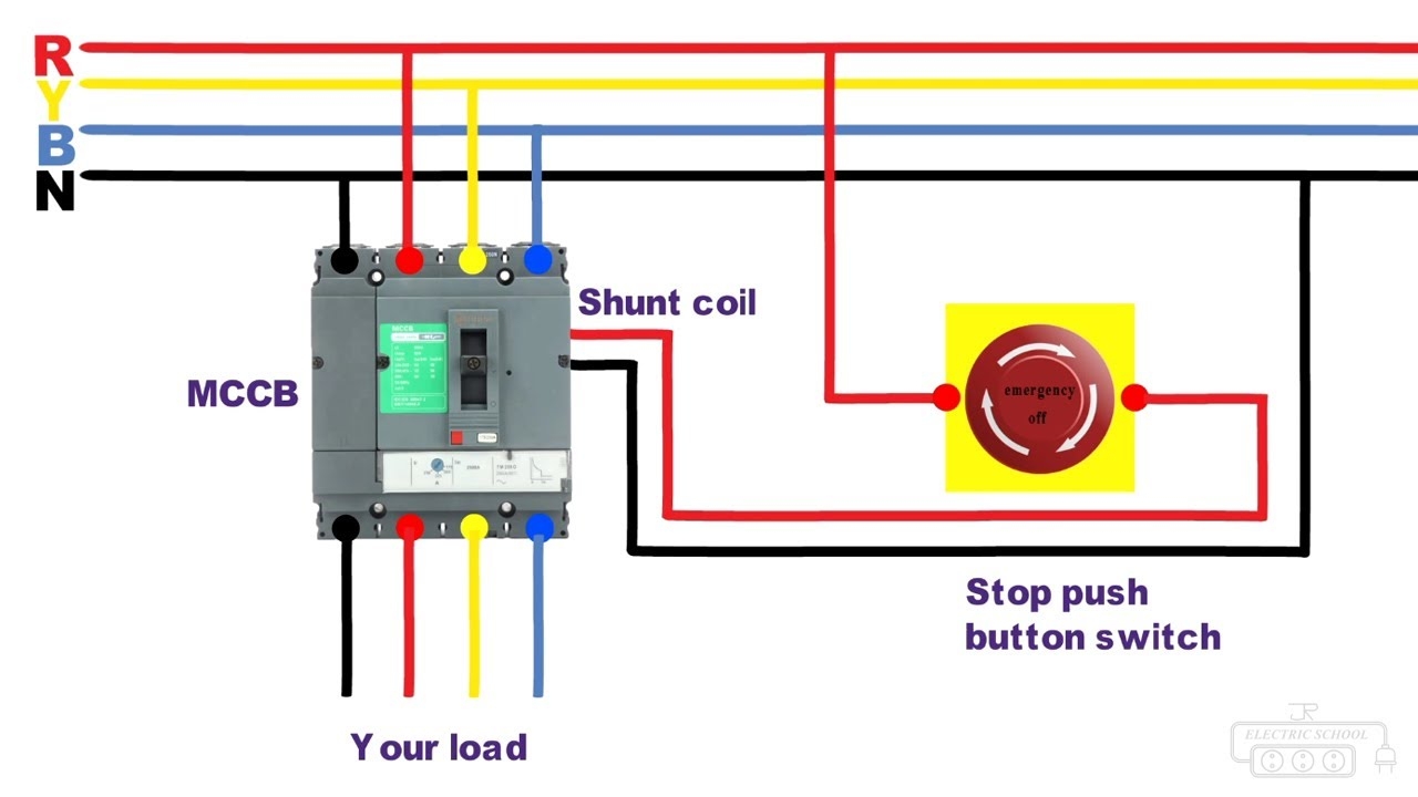
Shunt Trip Breaker Wiring Diagram JrElectricSchool YouTube
The image title is Shunt Trip Breaker Wiring Diagram JrElectricSchool YouTube, features dimensions of width 1280 px and height 720 px, with a file size of 1280 x 720 px. This image image/jpeg type visual are source from m.youtube.com.
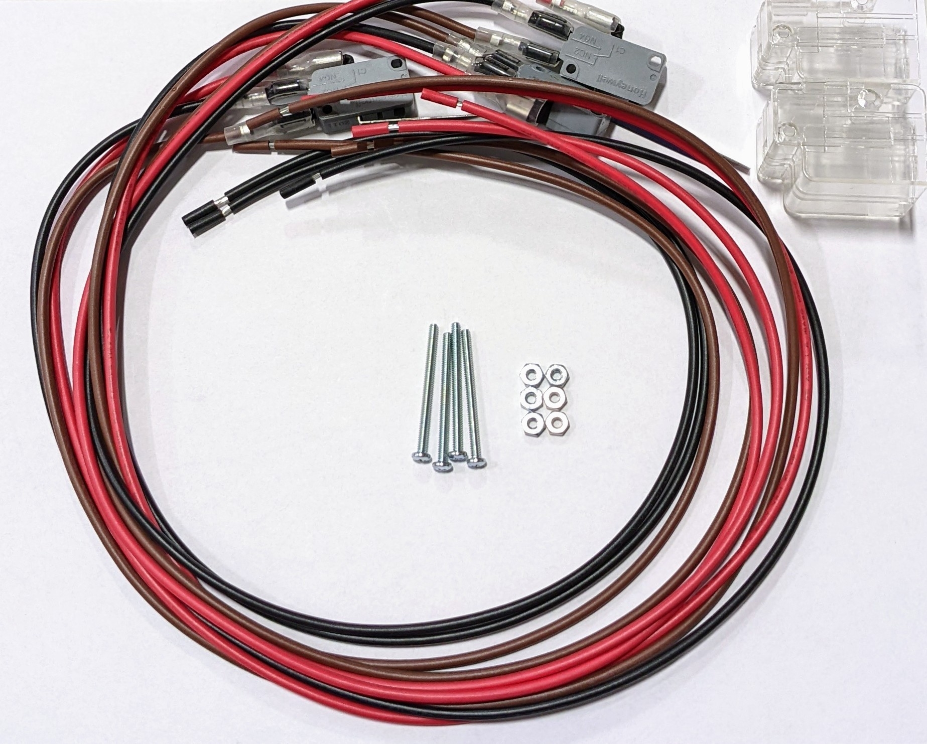
423880 Ansul Micro Switch 3 Pack National Fire Supply
The image title is 423880 Ansul Micro Switch 3 Pack National Fire Supply, features dimensions of width 1847 px and height 1483 px, with a file size of 1847 x 1483 px. This image image/jpeg type visual are source from nationalfiresupply.com.
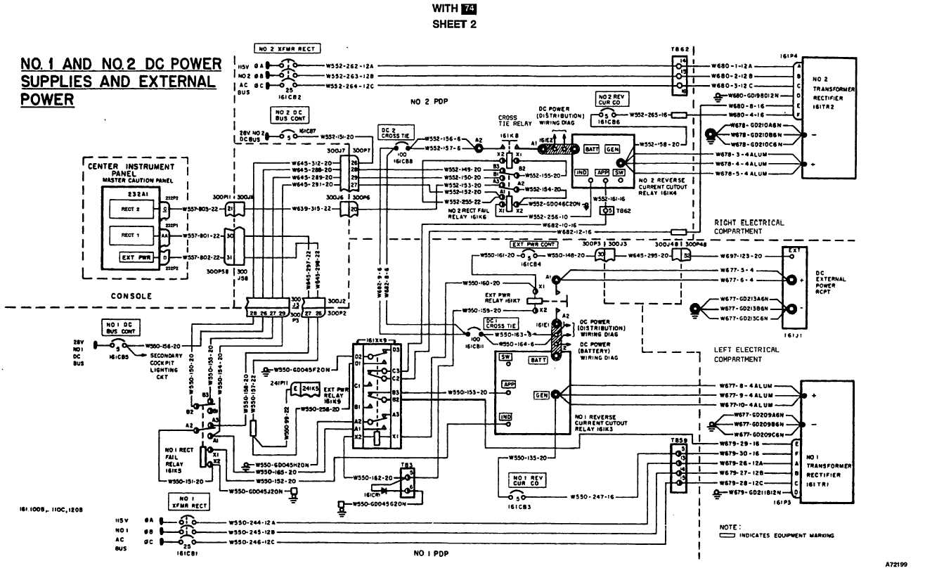
DC POWER SYSTEM WIRING DIAGRAM Continued TM 55 1520 240 T 2 511
The image title is DC POWER SYSTEM WIRING DIAGRAM Continued TM 55 1520 240 T 2 511, features dimensions of width 1316 px and height 815 px, with a file size of 1316 x 815. This image image/jpeg type visual are source from ch-47helicopters.tpub.com.
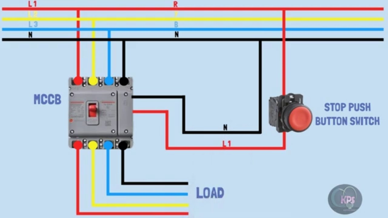
SHUNT TRIP BREAKER WIRING DIAGRAM SHUNT TRIP CONNECTION VIDEO ANIMATION YouTube
The image title is SHUNT TRIP BREAKER WIRING DIAGRAM SHUNT TRIP CONNECTION VIDEO ANIMATION YouTube, features dimensions of width 1280 px and height 720 px, with a file size of 1280 x 720. This image image/jpeg type visual are source from www.youtube.com.
Submittal Drawing
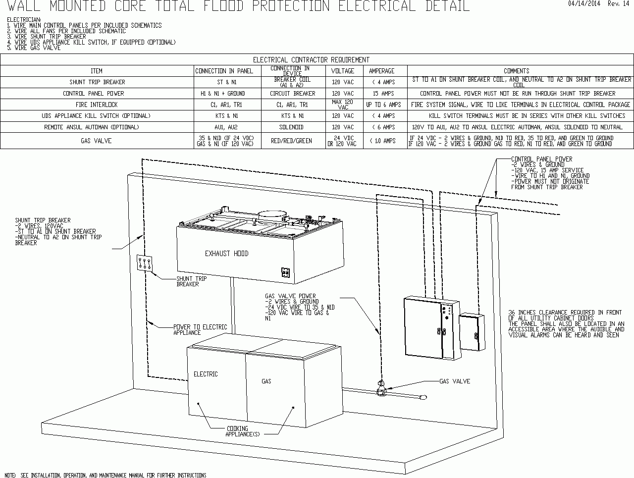
The image title is Submittal Drawing, features dimensions of width 1280 px and height 965 px, with a file size of 1280 x 965. This image image/gif type visual are source from www.captiveaire.com
FIRE EXTINGUISHING SYSTEM WIRING DIAGRAM
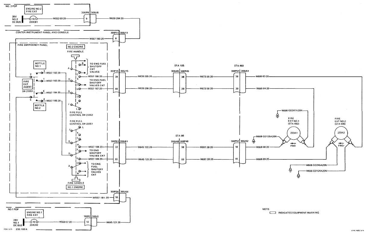
The image title is FIRE EXTINGUISHING SYSTEM WIRING DIAGRAM, features dimensions of width 1218 px and height 773 px, with a file size of 1218 x 773. This image image/jpeg type visual are source from ch-47helicopters.tpub.com.
Ansul System For Kitchen Help R Electricians
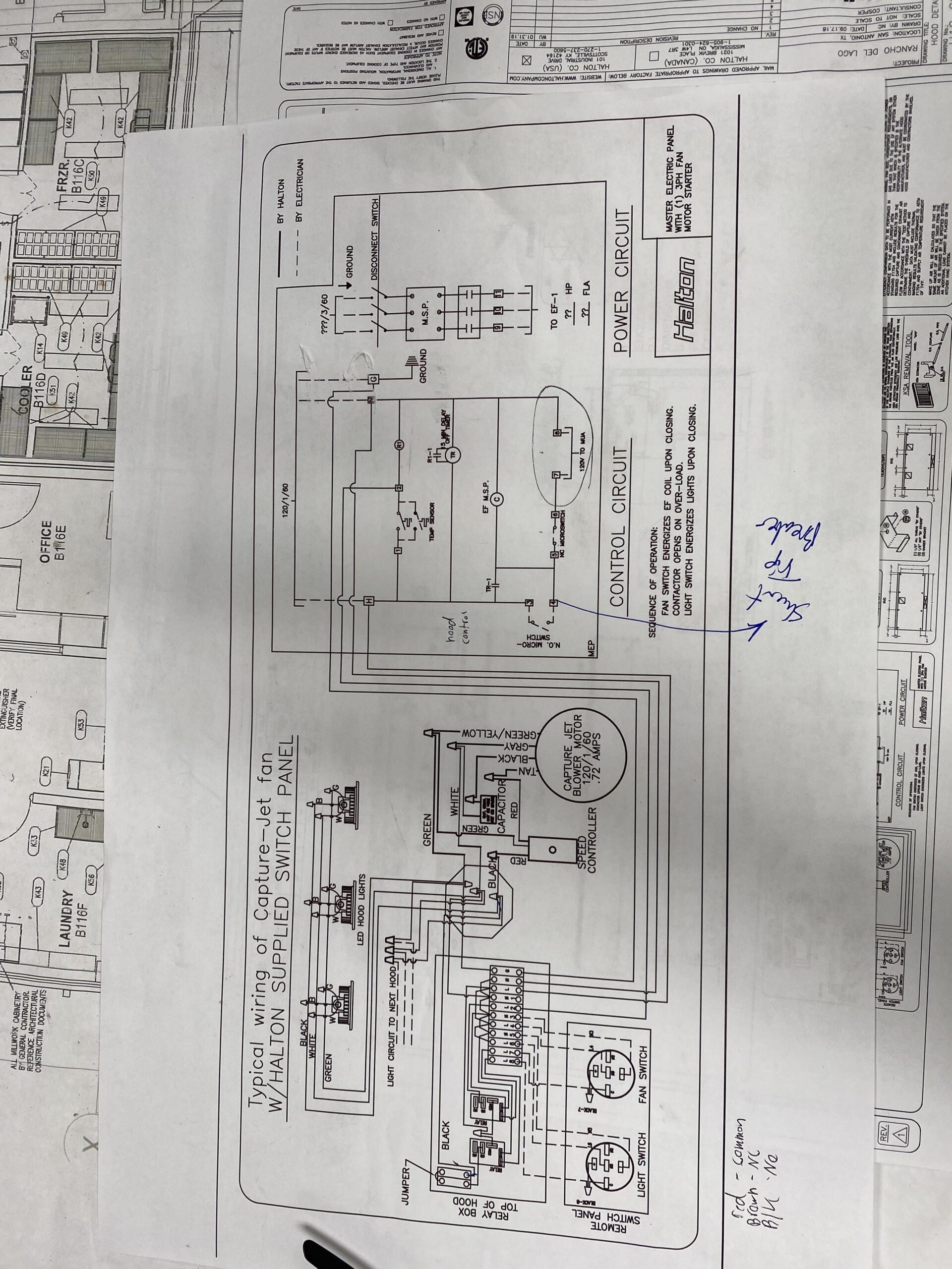
The image title is Ansul System For Kitchen Help R Electricians, features dimensions of width 1920 px and height 2560 px, with a file size of 3024 x 4032. This image image/jpeg type visual are source from www.reddit.com.
Kitchen Hood Non Shunt Trip YouTube
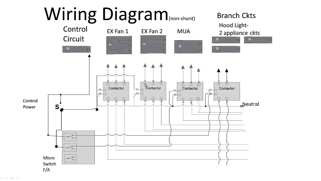
The image title is Kitchen Hood Non Shunt Trip YouTube, features dimensions of width 1280 px and height 720 px, with a file size of 1280 x 720.
The images on this page, sourced from Google for educational purposes, may be copyrighted. If you own an image and wish its removal or have copyright concerns, please contact us. We aim to promptly address these issues in compliance with our copyright policy and DMCA standards. Your cooperation is appreciated.
Related Keywords to Ansul System Wiring Diagram:
ansul system wiring diagram,ansul system wiring diagram pdf,ansul system wiring schematic,kitchen ansul system wiring diagram,shunt trip ansul system wiring diagram
