Table of Contents
The Value of A C Contactor Wiring Diagram
The Significance of A C Contactor Wiring Diagram
A C contactors play a crucial role in the operation of air conditioning systems, controlling the flow of electricity to the compressor and other components. Understanding the wiring diagram of an A C contactor is essential for troubleshooting, maintenance, and installation tasks. By deciphering the wiring diagram, technicians can identify connections, voltage ratings, and relay configurations, ensuring the proper functioning of the system. Let’s delve into the intricacies of an A C contactor wiring diagram and explore its value in the HVAC industry.
Interpreting the Wiring Diagram
The wiring diagram of an A C contactor provides a visual representation of the electrical connections within the unit. It outlines how various terminals are interconnected, indicating the path of electricity flow and the function of each component. By analyzing the wiring diagram, technicians can troubleshoot issues such as faulty connections, damaged wires, or malfunctioning relays. This comprehensive guide serves as a roadmap for ensuring the proper installation and maintenance of A C contactors.
Identifying Components and Terminals
One of the key benefits of a wiring diagram is its ability to label components and terminals within the A C contactor. By understanding the role of each terminal, technicians can accurately connect wires and ensure proper circuit operation. From power supply connections to control wiring, the diagram provides a detailed overview of how the contactor is structured. This knowledge is invaluable for troubleshooting issues and implementing repairs effectively.
Ensuring Safety and Compliance
Another critical aspect of utilizing a wiring diagram is ensuring safety and compliance with industry standards. By following the guidelines outlined in the diagram, technicians can prevent electrical hazards, short circuits, and equipment damage. Adhering to the wiring diagram specifications also ensures that the A C contactor operates within its designated voltage and current ratings, maintaining optimal performance and longevity. This commitment to safety and compliance is essential in the HVAC industry to safeguard both technicians and equipment.
Enhancing Efficiency and Accuracy
Having a thorough understanding of the A C contactor wiring diagram enhances efficiency and accuracy in troubleshooting and installation tasks. By referencing the diagram, technicians can quickly identify issues, make precise connections, and streamline the repair process. This level of proficiency not only saves time but also minimizes errors and ensures the correct functioning of the air conditioning system. The wiring diagram serves as a valuable tool for improving workflow and achieving reliable results in HVAC maintenance.
Related to A C Contactor Wiring Diagram
- 8n Ford Tractor Wiring Diagram
- 9 Lead Motor Wiring Diagram
- A C Capacitor Wiring Diagram
- A C Compressor Wiring Diagram
- A C Condenser Wiring Diagram
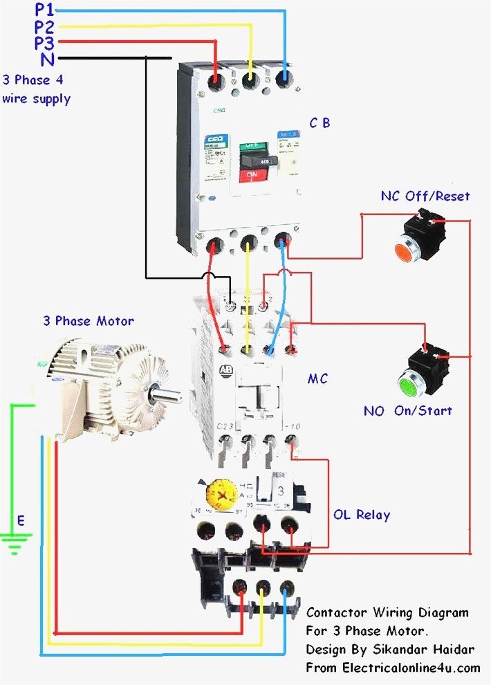
WAZIPOINT Engineering Science Technology Magnetic Contactor Connection Diagram
The image title is WAZIPOINT Engineering Science Technology Magnetic Contactor Connection Diagram, features dimensions of width 710 px and height 990 px, with a file size of 710 x 990 px. This image image/jpeg type visual are source from www.wazipoint.com.
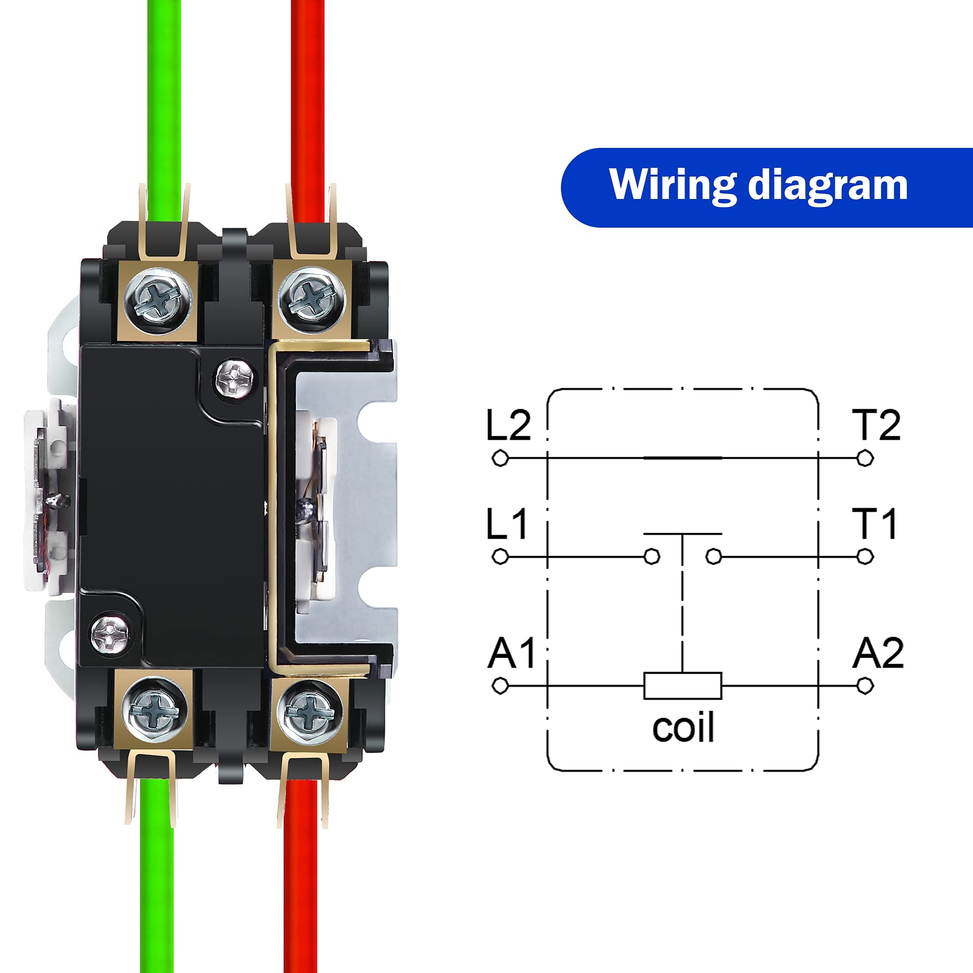
Carrier HVAC Motor Contactor 24VAC 30 Amp Coil Single Pole 1 Pole Furnace Replacement Relays Air Conditioner Heat Pump Refrigeration Systems Amazon Industrial Scientific
The image title is Carrier HVAC Motor Contactor 24VAC 30 Amp Coil Single Pole 1 Pole Furnace Replacement Relays Air Conditioner Heat Pump Refrigeration Systems Amazon Industrial Scientific, features dimensions of width 2000 px and height 2000 px, with a file size of 2000 x 2000 px. This image image/jpeg type visual are source from www.amazon.com.
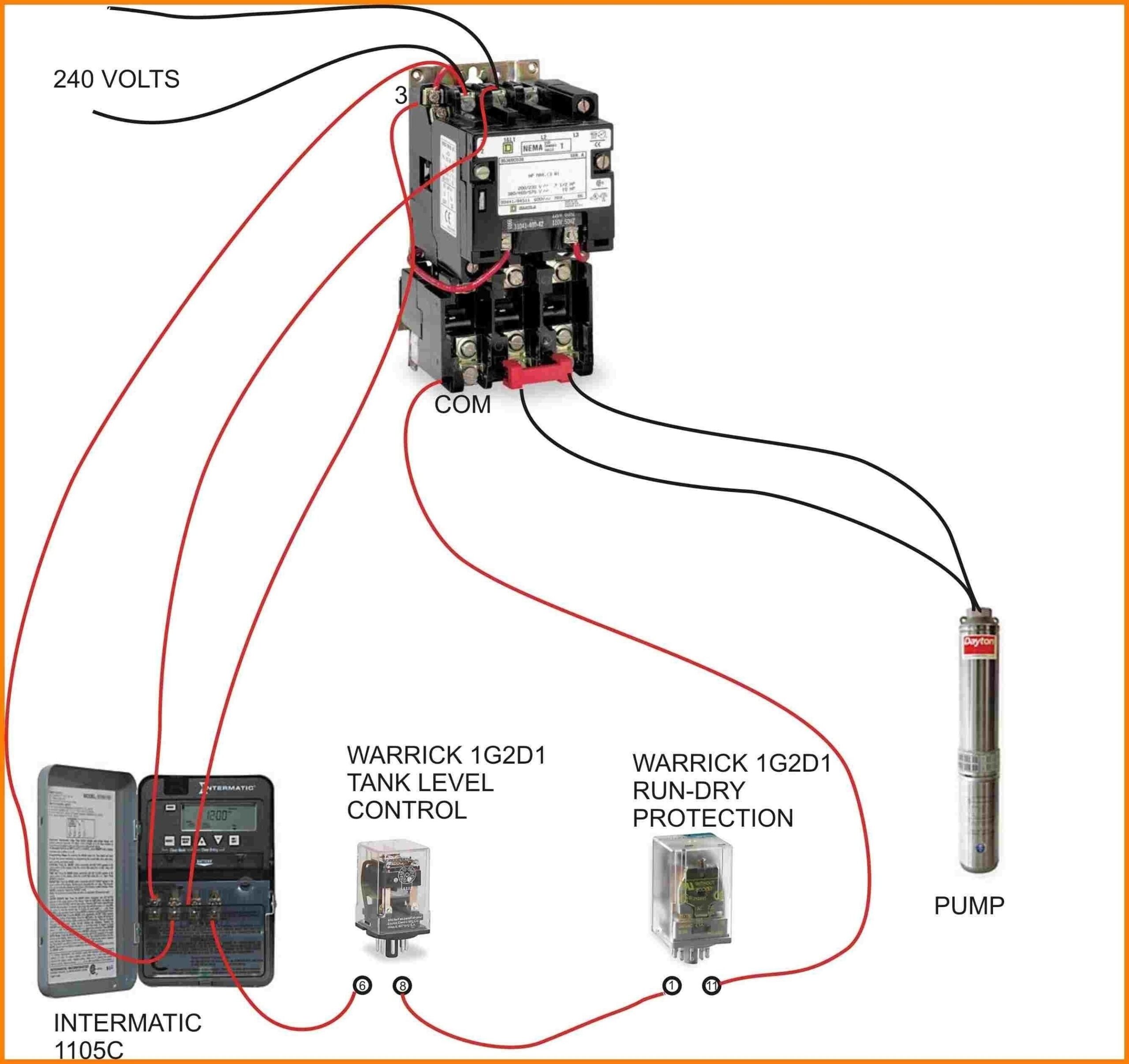
Magnetic Contactor Wiring Diagram Electrical Circuit Diagram Electrical Wiring Diagram Well Pump
The image title is Magnetic Contactor Wiring Diagram Electrical Circuit Diagram Electrical Wiring Diagram Well Pump, features dimensions of width 2560 px and height 2413 px, with a file size of 2668 x 2515. This image image/jpeg type visual are source from www.pinterest.com.
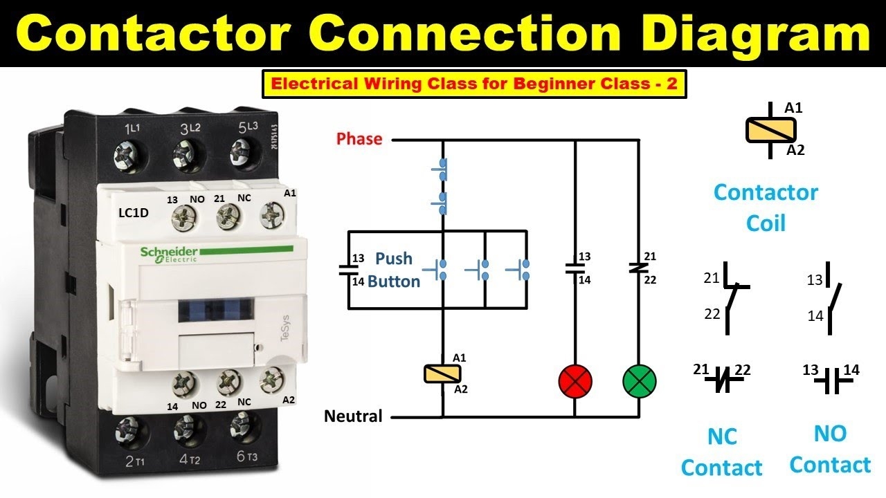
How To Do Contactor Wiring Electrical Wiring Class For Beginner Class 2 TheElectricalGuy YouTube
The image title is How To Do Contactor Wiring Electrical Wiring Class For Beginner Class 2 TheElectricalGuy YouTube, features dimensions of width 1280 px and height 720 px, with a file size of 1280 x 720. This image image/jpeg type visual are source from m.youtube.com.
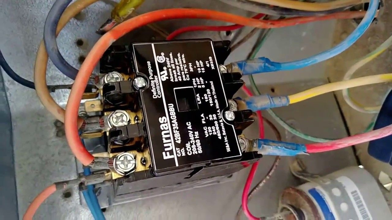
Pin On Maintenance Work In Dubai
The image title is Pin On Maintenance Work In Dubai, features dimensions of width 1280 px and height 720 px, with a file size of 1280 x 720. This image image/jpeg type visual are source from www.pinterest.com
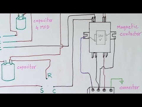
Ac Outdoor Unit Magnetic Contactor Diagram YouTube
The image title is Ac Outdoor Unit Magnetic Contactor Diagram YouTube, features dimensions of width 480 px and height 360 px, with a file size of 480 x 360. This image image/jpeg type visual are source from www.youtube.com.
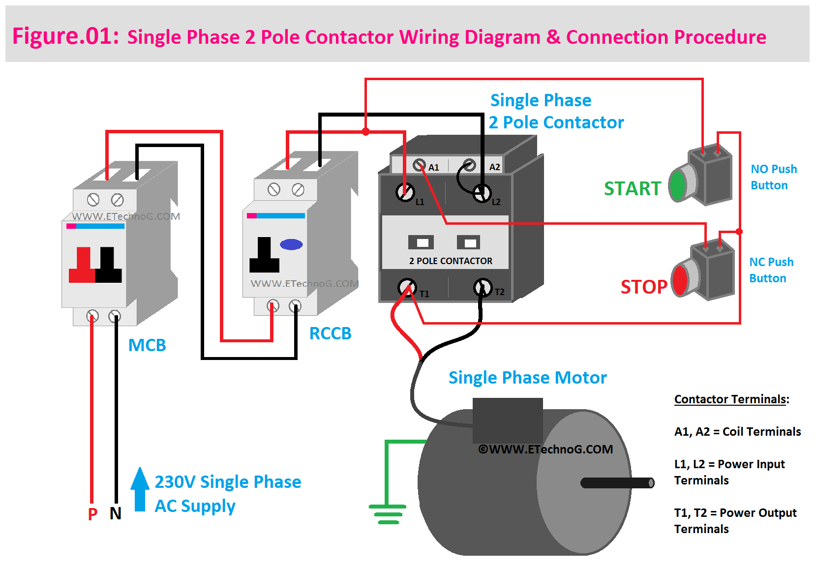
Single Phase 2 Pole Contactor Wiring Diagram Electrical Diagram Electrical Circuit Diagram Pole
The image title is Single Phase 2 Pole Contactor Wiring Diagram Electrical Diagram Electrical Circuit Diagram Pole, features dimensions of width 1661 px and height 1157 px, with a file size of 1661 x 1157. This image image/png type visual are source from www.pinterest.com.
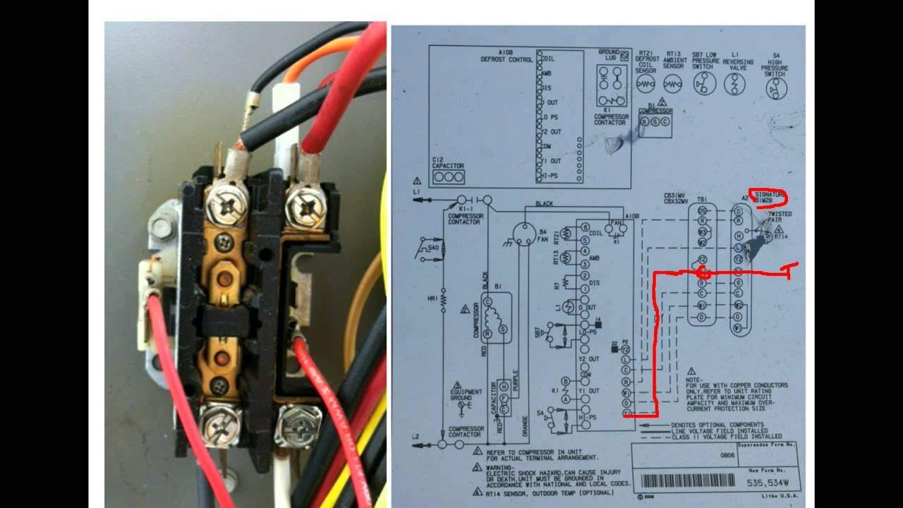
HVAC Training Understanding Schematics Contactors 2 YouTube
The image title is HVAC Training Understanding Schematics Contactors 2 YouTube, features dimensions of width 1280 px and height 720 px, with a file size of 1280 x 720.
The images on this page, sourced from Google for educational purposes, may be copyrighted. If you own an image and wish its removal or have copyright concerns, please contact us. We aim to promptly address these issues in compliance with our copyright policy and DMCA standards. Your cooperation is appreciated.
Related Keywords to A C Contactor Wiring Diagram:
a c contactor wiring diagram,how does a contactor switch work,how is a contactor wired,how to connect a contactor diagram,what is a contactor switch
