Table of Contents
Wiring Diagram For Well Pump
Wiring Diagram For Well Pump: A Comprehensive Guide
When it comes to ensuring your well pump operates efficiently and effectively, having a clear understanding of the wiring diagram is essential. A well pump is a crucial component of any water system, whether it’s for residential, agricultural, or industrial use. By having a well-designed wiring diagram, you can troubleshoot issues, make necessary repairs, and even install a new well pump with confidence. In this article, we will delve into the world of well pump wiring diagrams, exploring the intricacies of their design and functionality to empower you with the knowledge needed to keep your water system running smoothly.
The Basics of Well Pump Wiring Diagrams
Before we dive into the specifics of wiring diagrams for well pumps, it’s important to understand the basic components and principles involved. A well pump typically consists of a motor, control box, pressure switch, and power supply. The wiring diagram serves as a roadmap that illustrates how these components are connected and powered to ensure the well pump operates as intended.
Key Components in a Well Pump Wiring Diagram
Motor: The motor is responsible for driving the pump to draw water from the well.
Control Box: The control box houses the electrical components that regulate the pump’s operation.
Pressure Switch: The pressure switch monitors the water pressure and activates the pump as needed.
Power Supply: The power supply provides the electrical energy needed to run the well pump.
Understanding Different Types of Well Pump Wiring Diagrams
Well pump wiring diagrams come in various configurations, depending on the type of pump and the system it’s connected to. Common types include single-phase, three-phase, submersible, and jet pump wiring diagrams. Each type is tailored to the specific requirements of the pump, ensuring optimal performance and efficiency.
Single-Phase vs. Three-Phase Wiring Diagrams
Single-phase well pump wiring diagrams are designed for pumps that operate on a single alternating current (AC) voltage. In contrast, three-phase wiring diagrams are used for pumps that require three AC voltages for operation. Understanding the difference between these two types of diagrams is crucial for proper installation and maintenance of well pumps.
Submersible vs. Jet Pump Wiring Diagrams
Submersible well pumps are installed underwater in the well, while jet pumps are located above ground. As a result, their wiring diagrams differ to accommodate their unique installation requirements. Submersible pump diagrams detail how to connect the pump to the control box and power supply underwater, while jet pump diagrams focus on above-ground connections.
Benefits of Having a Well-Designed Wiring Diagram
Having a well-designed wiring diagram for your well pump offers several advantages. First and foremost, it provides a clear visual representation of how the pump is wired, making troubleshooting and repairs easier and more efficient. Additionally, a well-crafted wiring diagram ensures that the pump operates safely and reliably, reducing the risk of electrical issues or malfunctions.
Tips for Creating and Using Well Pump Wiring Diagrams
Consult the manufacturer’s instructions for specific guidance on creating a wiring diagram.
Label each component and connection point on the diagram for clarity and ease of use.
Regularly inspect and update the wiring diagram to reflect any changes or modifications to the pump system.
Keep a copy of the wiring diagram in a safe and accessible location for quick reference in case of emergencies.
Conclusion
In conclusion, a well-designed wiring diagram is a valuable resource for anyone responsible for the installation, maintenance, or repair of a well pump system. By understanding the basics of well pump wiring diagrams and their various types, you can ensure that your water system operates smoothly and efficiently. Remember to follow best practices when creating and using wiring diagrams to maximize their effectiveness and keep your well pump in optimal working condition.
Related to Wiring Diagram For Well Pump
- Wiring Diagram For Travel Trailer
- Wiring Diagram For Two Switches To One Light
- Wiring Diagram For Universal Ignition Switch
- Wiring Diagram For Usb
- Wiring Diagram For Warn Winch
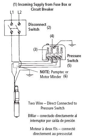
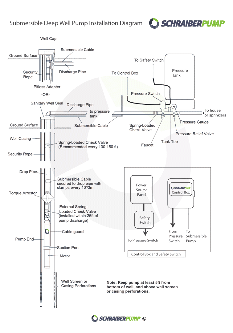
Green Road Farm Submersible Well Pump Installation Troubleshooting Well Pump Pressure Switch Submersible Well Pump Well Pump
The image title is Green Road Farm Submersible Well Pump Installation Troubleshooting Well Pump Pressure Switch Submersible Well Pump Well Pump, features dimensions of width 289 px and height 457 px, with a file size of 289 x 457 px. This image image/jpeg type visual are source from www.pinterest.com.
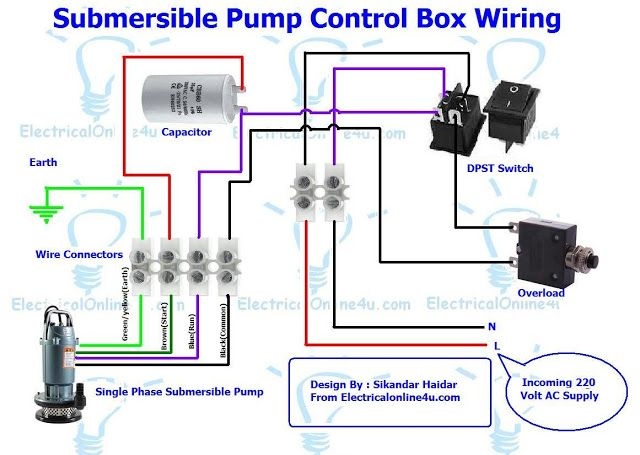
Single Phase 3 Wire Submersible Pump Control Box Wiring Diagram Submersible Pump Well Pump Electrical Diagram
The image title is Single Phase 3 Wire Submersible Pump Control Box Wiring Diagram Submersible Pump Well Pump Electrical Diagram, features dimensions of width 640 px and height 455 px, with a file size of 640 x 455 px. This image image/jpeg type visual are source from www.pinterest.com.
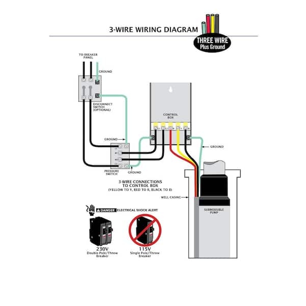
ECO FLO 3 4 HP Control Box For 4 In Well Pump EFCB7 HD The Home Depot
The image title is ECO FLO 3 4 HP Control Box For 4 In Well Pump EFCB7 HD The Home Depot, features dimensions of width 600 px and height 600 px, with a file size of 600 x 600. This image image/jpeg type visual are source from www.homedepot.com.
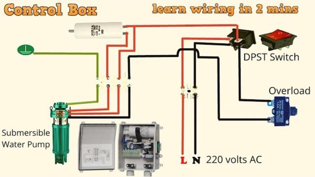
Submersible Water Pump Control Panel Wiring Diagram Electrical Technologies YouTube
The image title is Submersible Water Pump Control Panel Wiring Diagram Electrical Technologies YouTube, features dimensions of width 1280 px and height 720 px, with a file size of 1280 x 720. This image image/jpeg type visual are source from m.youtube.com.
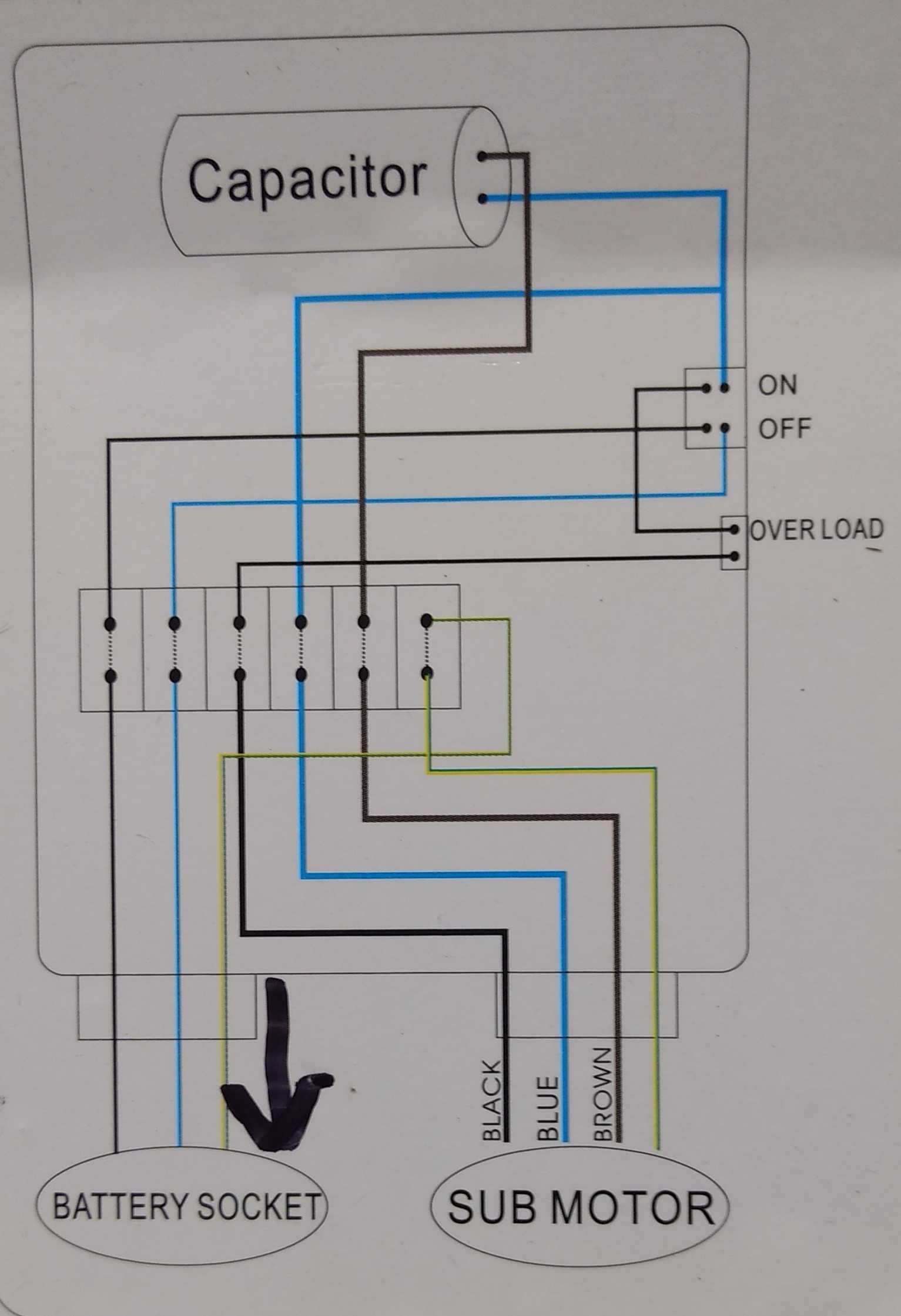
Plumbing Confusion About Wiring Control Box For A Submersible Well Pump Home Improvement Stack Exchange
The image title is Plumbing Confusion About Wiring Control Box For A Submersible Well Pump Home Improvement Stack Exchange, features dimensions of width 756 px and height 1081 px, with a file size of 756 x 1081. This image image/png type visual are source from diy.stackexchange.com
Plumbing Confusion About Wiring Control Box For A Submersible Well Pump Home Improvement Stack Exchange
The image title is Plumbing Confusion About Wiring Control Box For A Submersible Well Pump Home Improvement Stack Exchange, features dimensions of width 1533 px and height 2241 px, with a file size of 1533 x 2241. This image image/jpeg type visual are source from diy.stackexchange.com.
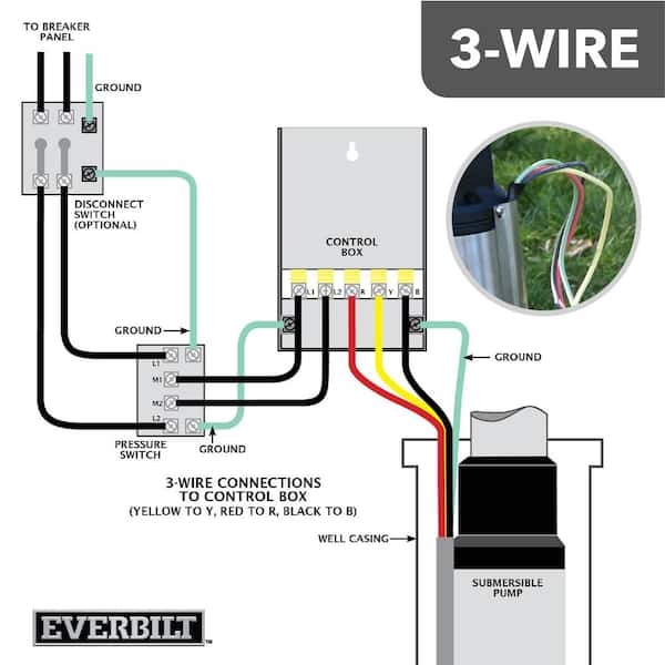
Everbilt 1 2 HP Submersible 3 Wire Motor 10 GPM Deep Well Potable Water Pump EFSUB5 123HD The Home Depot
The image title is Everbilt 1 2 HP Submersible 3 Wire Motor 10 GPM Deep Well Potable Water Pump EFSUB5 123HD The Home Depot, features dimensions of width 600 px and height 600 px, with a file size of 600 x 600. This image image/jpeg type visual are source from www.homedepot.com.
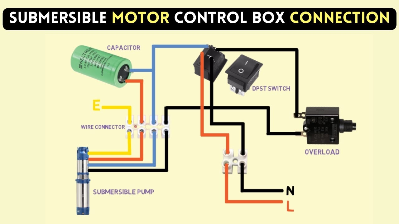
Submersible Pump Control Box Wiring Diagram For 3 Wire Single Phase YouTube
The image title is Submersible Pump Control Box Wiring Diagram For 3 Wire Single Phase YouTube, features dimensions of width 1280 px and height 720 px, with a file size of 1280 x 720.
The images on this page, sourced from Google for educational purposes, may be copyrighted. If you own an image and wish its removal or have copyright concerns, please contact us. We aim to promptly address these issues in compliance with our copyright policy and DMCA standards. Your cooperation is appreciated.
Related Keywords to Wiring Diagram For Well Pump:
wiring diagram for shallow well pump,wiring diagram for submersible pump,wiring diagram for submersible pump control box,wiring diagram for well pump,wiring diagram for well pump pressure switch
