Table of Contents
Wiring Diagram For A Capacitor
Exploring the Importance of Wiring Diagram For A Capacitor
When it comes to electrical circuits, capacitors play a crucial role in storing and releasing electrical energy. A wiring diagram for a capacitor serves as a blueprint that guides the proper installation and connection of capacitors in various electronic devices. Understanding the wiring diagram for a capacitor is essential for ensuring the efficient and safe operation of electronic equipment. Let’s delve into the significance of these diagrams and unravel the intricacies of capacitor wiring.
The Basics of Capacitors
Before we delve into wiring diagrams, let’s briefly touch upon the basics of capacitors. Capacitors are passive electronic components that store energy in an electric field. They are commonly used in circuits to smooth out voltage fluctuations, filter signals, and provide energy storage. Capacitors come in various types and sizes, each serving a specific purpose in electronic devices.
Importance of Wiring Diagrams
A wiring diagram for a capacitor provides a visual representation of how capacitors should be connected within a circuit. It outlines the proper placement of capacitor leads, polarity considerations, and overall circuit configuration. Following a wiring diagram ensures that capacitors are installed correctly, minimizing the risk of malfunctions or electrical hazards. Whether you are a seasoned electrical engineer or a DIY enthusiast, referencing a wiring diagram is crucial for precision and safety.
Components of a Wiring Diagram
A typical wiring diagram for a capacitor includes symbols representing capacitors, connecting wires, and other components in the circuit. It also specifies the values of capacitors, such as capacitance and voltage ratings, to ensure compatibility with the rest of the circuit. By understanding these components and their interconnections, you can effectively interpret and implement wiring diagrams for capacitors.
Common Capacitor Wiring Configurations
Capacitors can be wired in various configurations depending on the circuit requirements. Series and parallel connections are two common wiring setups for capacitors, each offering unique benefits in terms of capacitance, voltage handling, and overall circuit performance. By following the wiring diagram for a specific configuration, you can optimize the functionality of capacitors in your electronic projects.
Tips for Interpreting Wiring Diagrams
Pay attention to the orientation of capacitor symbols in the diagram to ensure correct polarity.
Follow the designated paths for connecting wires to prevent short circuits or incorrect connections.
Refer to the component values and ratings specified in the diagram to select appropriate capacitors for the circuit.
Double-check your connections against the wiring diagram before applying power to the circuit to avoid potential damage.
Conclusion
In conclusion, a wiring diagram for a capacitor is a valuable tool for anyone working with electronic circuits that incorporate capacitors. By understanding the importance of wiring diagrams and following them diligently, you can ensure the proper installation and operation of capacitors in your projects. Whether you are troubleshooting an existing circuit or designing a new one, referring to wiring diagrams will enhance efficiency, safety, and overall performance. Embrace the power of wiring diagrams for capacitors and elevate your electronics projects to new heights!
Related to Wiring Diagram For A Capacitor
- Wiring Diagram For A Alternator
- Wiring Diagram For A Bathroom
- Wiring Diagram For A Bedroom
- Wiring Diagram For A Boat Trailer
- Wiring Diagram For A Camper Trailer
Single Phase Permanent Capacitor Motor Wiring Diagram English YouTube
The image title is Single Phase Permanent Capacitor Motor Wiring Diagram English YouTube, features dimensions of width 1280 px and height 720 px, with a file size of 1280 x 720 px. This image image/jpeg type visual are source from m.youtube.com.
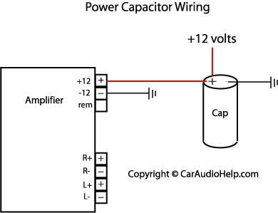
Car Audio Capacitor Installation
The image title is Car Audio Capacitor Installation, features dimensions of width 390 px and height 299 px, with a file size of 390 x 299 px. This image image/png type visual are source from www.caraudiohelp.com.
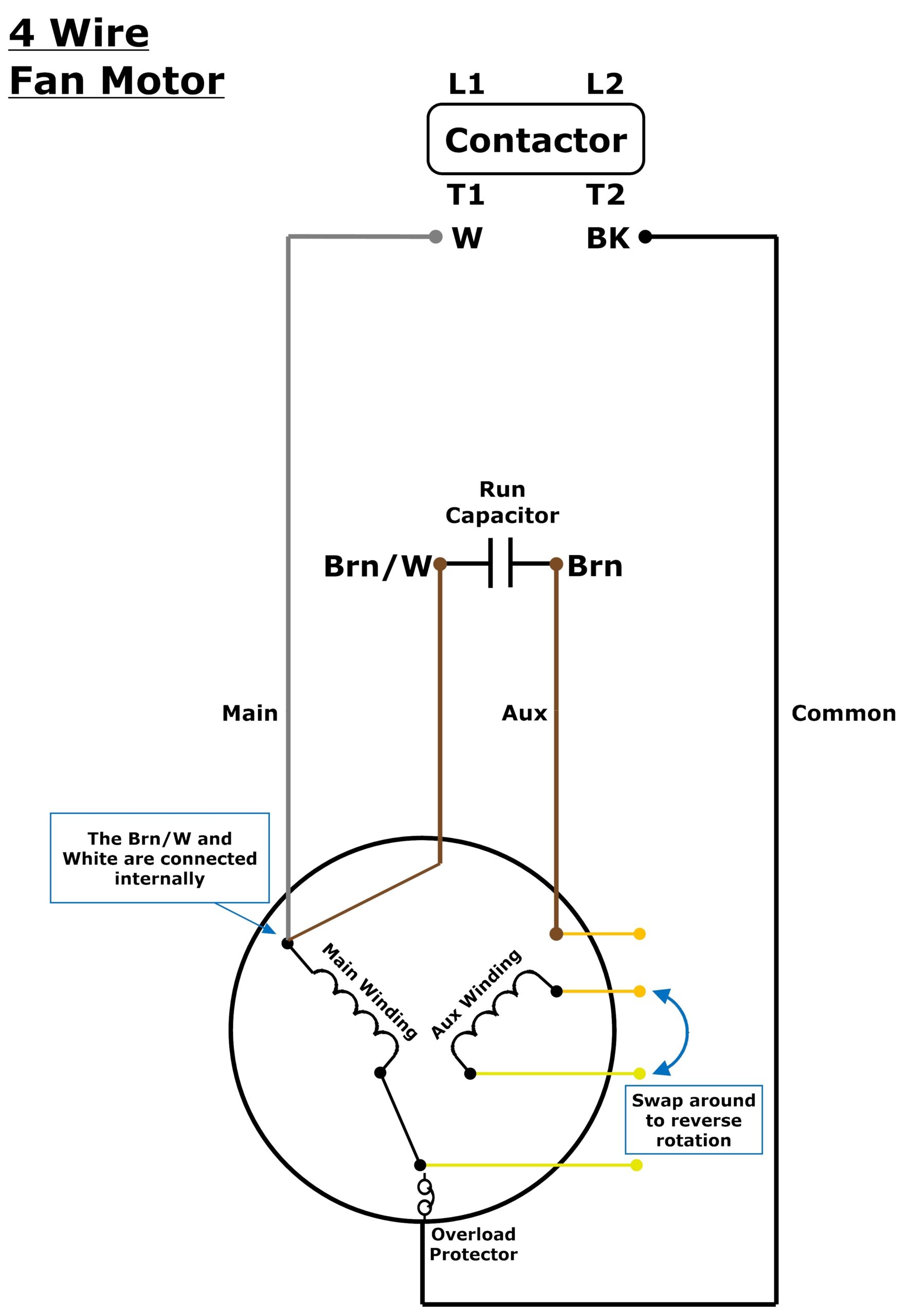
3 Or 4 Wire Condenser Fan Motor Wiring Johnstone Supply Support
The image title is 3 Or 4 Wire Condenser Fan Motor Wiring Johnstone Supply Support, features dimensions of width 1762 px and height 2560 px, with a file size of 2837 x 4123. This image image/jpeg type visual are source from support.johnstonehvac.biz.
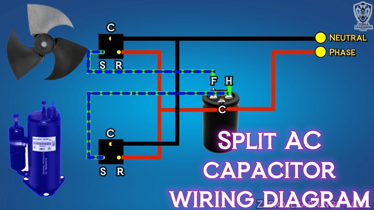
Split AC Capacitor Wiring Diagram Dual Capacitor HVAC Electrical YouTube
The image title is Split AC Capacitor Wiring Diagram Dual Capacitor HVAC Electrical YouTube, features dimensions of width 1280 px and height 720 px, with a file size of 1280 x 720. This image image/jpeg type visual are source from m.youtube.com.
Awesome Refrigerator Compressor Relay Wiring Diagram Electrical Wiring Diagram Electrical Circuit Diagram Refrigeration And Air Conditioning
The image title is Awesome Refrigerator Compressor Relay Wiring Diagram Electrical Wiring Diagram Electrical Circuit Diagram Refrigeration And Air Conditioning, features dimensions of width 1093 px and height 1285 px, with a file size of 1093 x 1285. This image image/jpeg type visual are source from www.pinterest.com
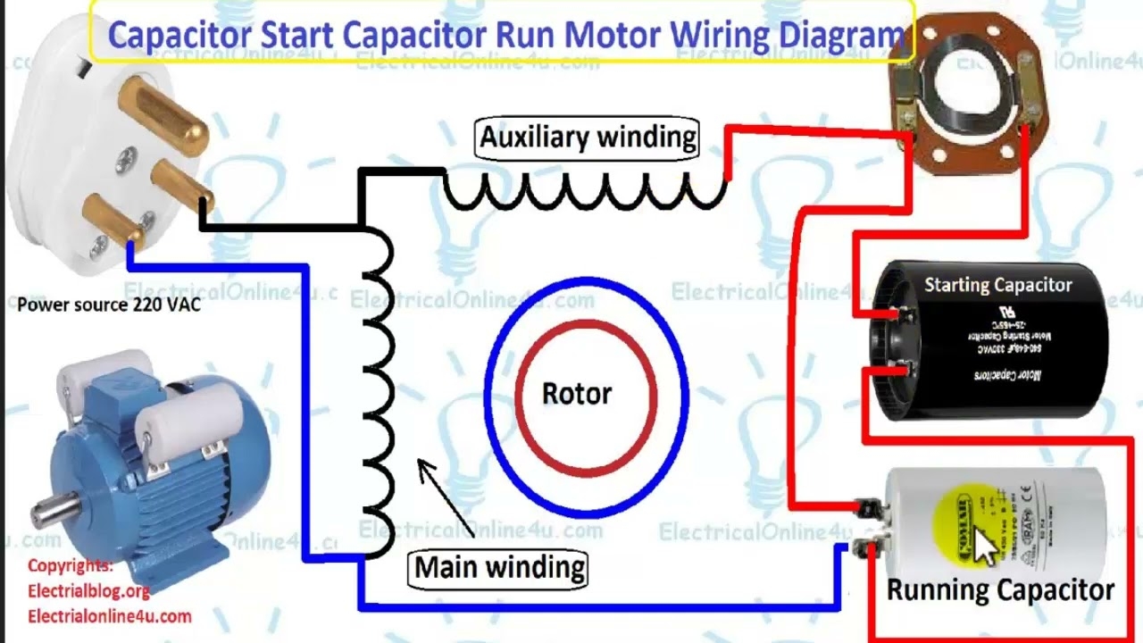
Single Phase Motor Wiring Diagram With Capacitor Start Capacitor Run English YouTube
The image title is Single Phase Motor Wiring Diagram With Capacitor Start Capacitor Run English YouTube, features dimensions of width 1280 px and height 720 px, with a file size of 1280 x 720. This image image/jpeg type visual are source from m.youtube.com.
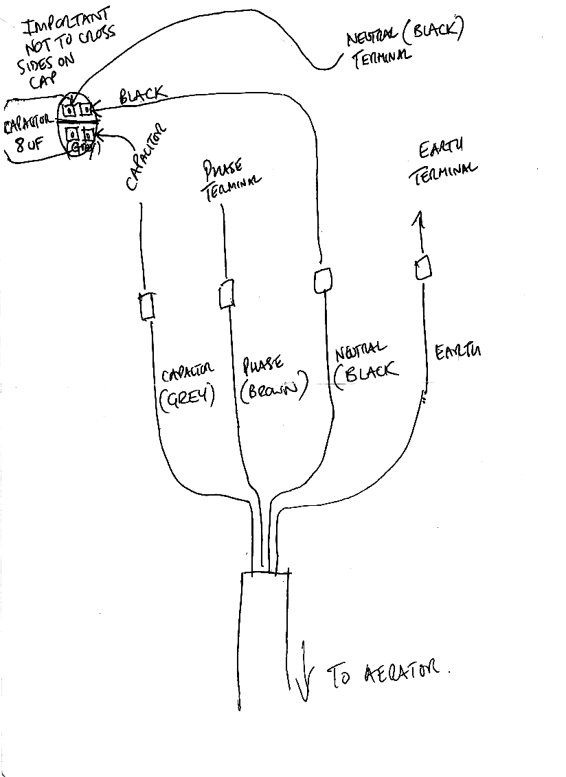
Help Understanding Wiring Of Capacitor Electrical Engineering Stack Exchange
The image title is Help Understanding Wiring Of Capacitor Electrical Engineering Stack Exchange, features dimensions of width 824 px and height 1132 px, with a file size of 824 x 1132. This image image/png type visual are source from electronics.stackexchange.com.
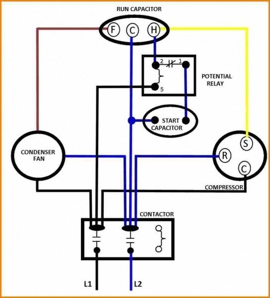
Capacitors For Compressor Wiring Diagram Ac Capacitor Hvac Compressor Air Compressor Motor
The image title is Capacitors For Compressor Wiring Diagram Ac Capacitor Hvac Compressor Air Compressor Motor, features dimensions of width 544 px and height 600 px, with a file size of 544 x 600.
The images on this page, sourced from Google for educational purposes, may be copyrighted. If you own an image and wish its removal or have copyright concerns, please contact us. We aim to promptly address these issues in compliance with our copyright policy and DMCA standards. Your cooperation is appreciated.
Related Keywords to Wiring Diagram For A Capacitor:
wiring diagram for a capacitor,wiring diagram for a capacitor start motor,wiring diagram for ac capacitor,wiring diagram for capacitor run motor,wiring diagram for capacitor start fan motor

