Table of Contents
Exploring the Value of Wiring A Contactor Diagram
Wiring a contactor diagram is a crucial step in many electrical projects, whether you’re working on a residential, commercial, or industrial system. This detailed schematic not only guides you through the process of connecting various components but also plays a vital role in ensuring the safety and efficiency of the electrical setup. Understanding how to wire a contactor diagram can simplify complex wiring tasks, prevent costly errors, and streamline troubleshooting processes. Let’s delve into the world of wiring a contactor diagram to uncover its significance and practical applications.
The Basics of Contactor Wiring
Before we dive into the intricacies of wiring a contactor diagram, let’s establish a foundation by discussing the basics of contactor wiring. A contactor is an electrical relay that controls the flow of electricity to a load, such as a motor or lighting system. It consists of contacts that open and close to establish or interrupt the electrical circuit. When wiring a contactor, it’s essential to understand the terminal markings, coil voltage, and contact configuration to ensure proper installation and operation.
Terminal Markings and Connections
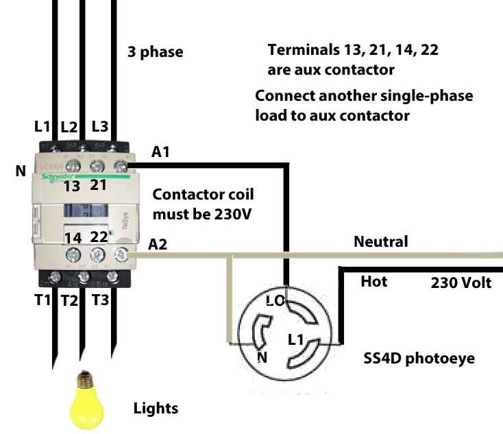
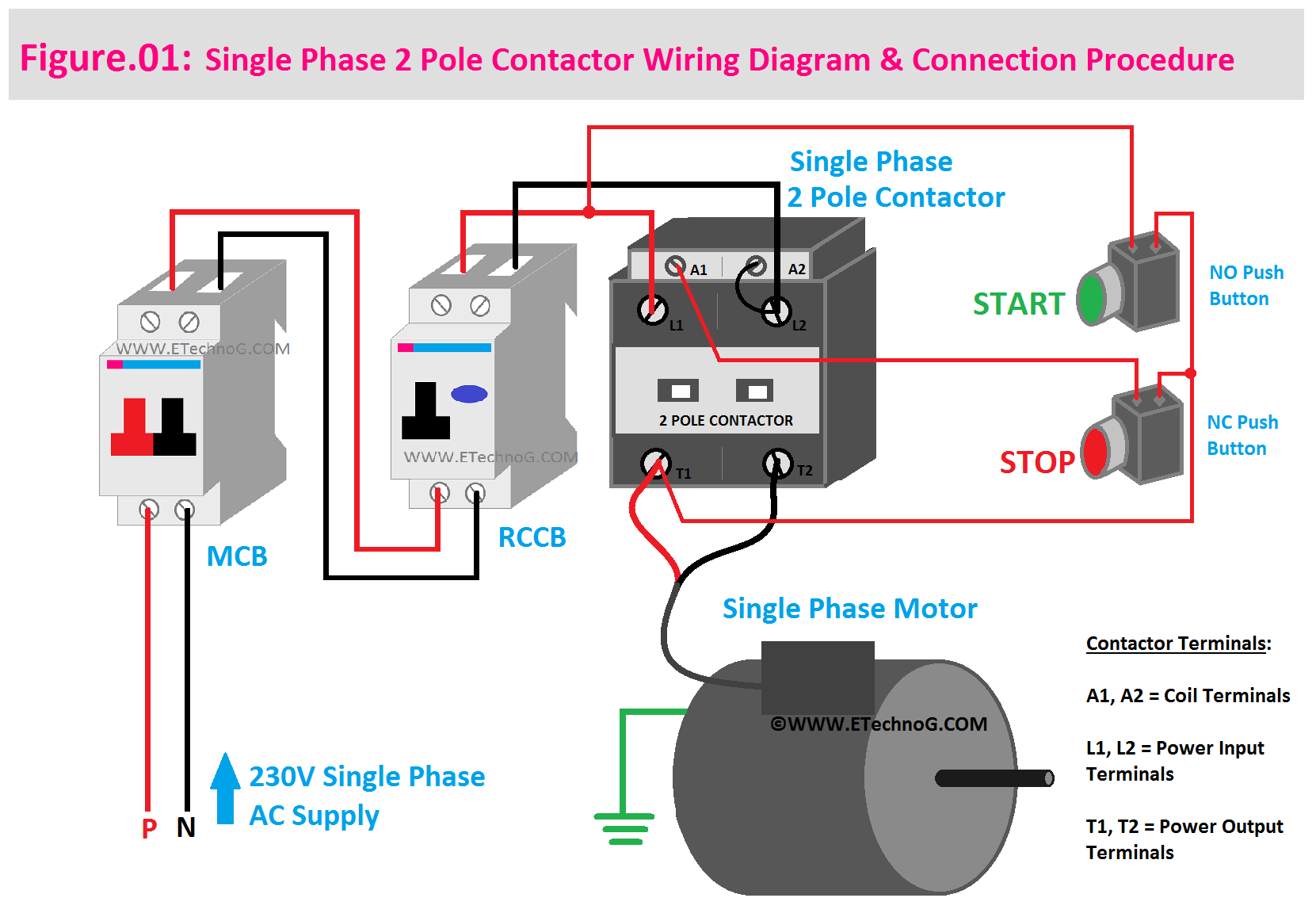
Contactor terminal markings can vary based on the manufacturer and model, but common designations include L1, L2, L3 for line voltage connections, T1, T2, T3 for load connections, A1, A2 for coil terminals, and auxiliary contacts for additional control functions. Familiarizing yourself with these terminal markings is crucial for accurately interpreting and implementing a contactor wiring diagram.
Coil Voltage and Control Circuit
The coil voltage of a contactor determines the voltage required to energize the coil and activate the contacts. It’s essential to match the coil voltage with the control circuit voltage to ensure compatibility and reliable operation. Understanding the relationship between the coil voltage, control circuit, and power supply is essential for successful contactor wiring.
Benefits of Wiring A Contactor Diagram
Now that we’ve covered the fundamentals of contactor wiring, let’s explore the specific benefits of creating and using a contactor diagram in your electrical projects. By incorporating a detailed wiring diagram, you can:
- Ensure accurate and consistent wiring connections
- Facilitate troubleshooting and maintenance procedures
- Minimize errors and reduce the risk of electrical faults
- Enhance overall system reliability and safety
Step-by-Step Guide to Wiring A Contactor Diagram
To harness the full potential of a contactor diagram, it’s essential to follow a systematic approach when wiring the components. Here’s a step-by-step guide to wiring a contactor diagram:
- Identify the contactor terminals and their respective functions
- Determine the coil voltage and control circuit requirements
- Refer to the contactor wiring diagram for guidance on proper connections
- Securely fasten wiring connections and verify continuity using a multimeter
- Energize the coil and test the contactor operation to ensure functionality
Conclusion
In conclusion, understanding the value of wiring a contactor diagram is essential for anyone involved in electrical installations, repairs, or maintenance. By embracing the insights provided by a well-crafted diagram, you can navigate complex wiring tasks with confidence, precision, and efficiency. Whether you’re a seasoned electrician or a DIY enthusiast, mastering the art of interpreting and implementing a contactor wiring diagram can elevate your skills and elevate your electrical projects to new heights.
Related to Wiring A Contactor Diagram
- Wiring A Alternator Diagram
- Wiring A Backup Camera Diagram
- Wiring A Boat Trailer Diagram
- Wiring A Ceiling Light Diagram
- Wiring A Circuit Breaker Diagram
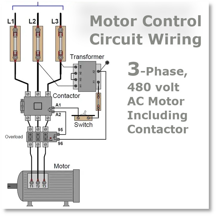
How To Wire Motor Control Contactor
The image title is How To Wire Motor Control Contactor, features dimensions of width 734 px and height 633 px, with a file size of 734 x 633 px. This image image/jpeg type visual are source from waterheatertimer.org.
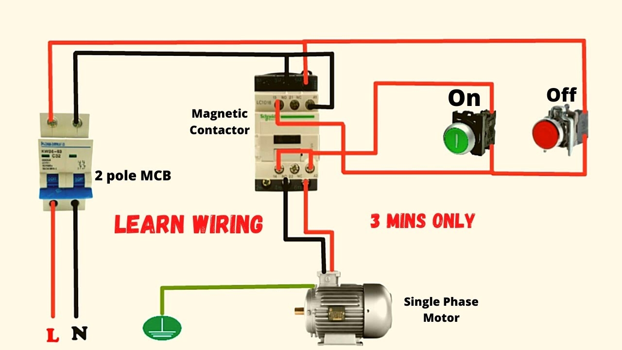
Single Phase 2 Pole Contactor Wiring Diagram Electrical Diagram Electrical Circuit Diagram Pole
The image title is Single Phase 2 Pole Contactor Wiring Diagram Electrical Diagram Electrical Circuit Diagram Pole, features dimensions of width 1661 px and height 1157 px, with a file size of 1661 x 1157 px. This image image/png type visual are source from www.pinterest.com.
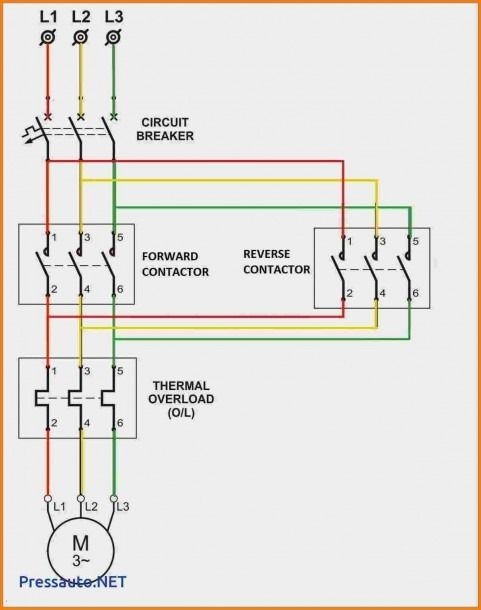
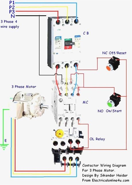
3 Phase Contactor Wiring Diagram Circuit Diagram Electrical Circuit Diagram Electrical Wiring Diagram
The image title is 3 Phase Contactor Wiring Diagram Circuit Diagram Electrical Circuit Diagram Electrical Wiring Diagram, features dimensions of width 481 px and height 610 px, with a file size of 481 x 610. This image image/jpeg type visual are source from www.pinterest.com.
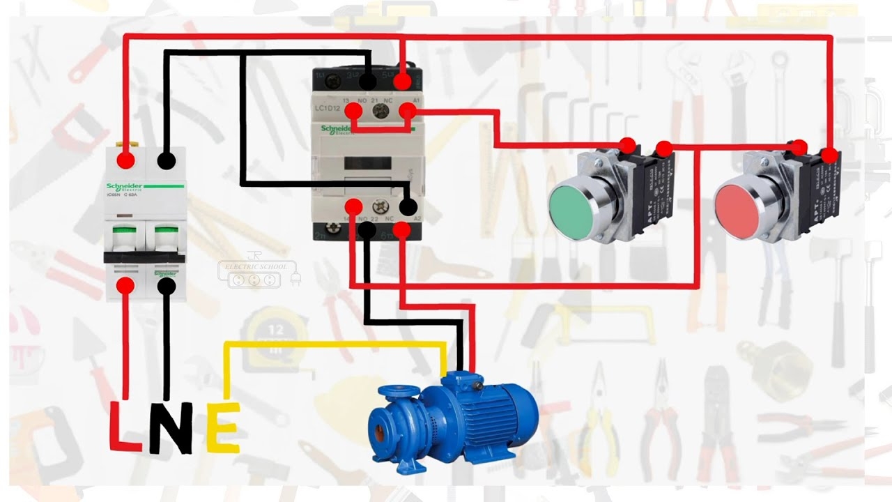
Single Phase Motor Connection With Magnetic Contactor Wiring Diagram YouTube
The image title is Single Phase Motor Connection With Magnetic Contactor Wiring Diagram YouTube, features dimensions of width 1280 px and height 720 px, with a file size of 1280 x 720. This image image/jpeg type visual are source from www.youtube.com.
Electric Contactor Wiring In Electric Motors Relectric
The image title is Electric Contactor Wiring In Electric Motors Relectric, features dimensions of width 724 px and height 724 px, with a file size of 724 x 724. This image image/jpeg type visual are source from www.relectric.com
Single Phase Motor Connection With Magnetic Contactor Wiring Diagram YouTube
The image title is Single Phase Motor Connection With Magnetic Contactor Wiring Diagram YouTube, features dimensions of width 1280 px and height 720 px, with a file size of 1280 x 720. This image image/jpeg type visual are source from www.youtube.com.
Magnetic Contactor Connection Diagram Magnetic Contactor Connection Diagram With A Electrical Circuit Diagram Electrical Wiring Diagram Home Electrical Wiring
The image title is Magnetic Contactor Connection Diagram Magnetic Contactor Connection Diagram With A Electrical Circuit Diagram Electrical Wiring Diagram Home Electrical Wiring, features dimensions of width 459 px and height 640 px, with a file size of 459 x 640. This image image/jpeg type visual are source from www.pinterest.com.
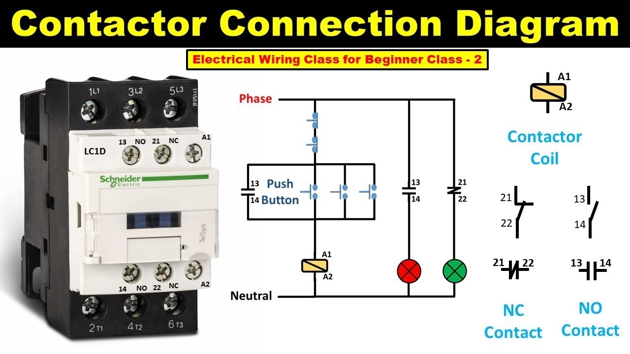
How To Do Contactor Wiring Electrical Wiring Class For Beginner Class 2 TheElectricalGuy YouTube
The image title is How To Do Contactor Wiring Electrical Wiring Class For Beginner Class 2 TheElectricalGuy YouTube, features dimensions of width 1280 px and height 720 px, with a file size of 1280 x 720.
The images on this page, sourced from Google for educational purposes, may be copyrighted. If you own an image and wish its removal or have copyright concerns, please contact us. We aim to promptly address these issues in compliance with our copyright policy and DMCA standards. Your cooperation is appreciated.
Related Keywords to Wiring A Contactor Diagram:
wiring a contactor diagram,wiring diagram contactor 1 phase,wiring diagram contactor 3 phase,wiring diagram contactor and timer,wiring diagram contactor symbol
