Table of Contents
Exploring the Value of Well Pump Control Box Wiring Diagram
The Significance of Well Pump Control Box Wiring Diagram
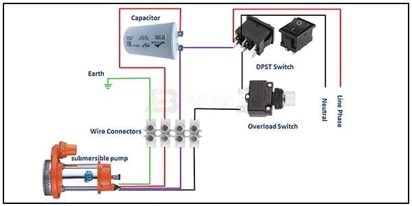
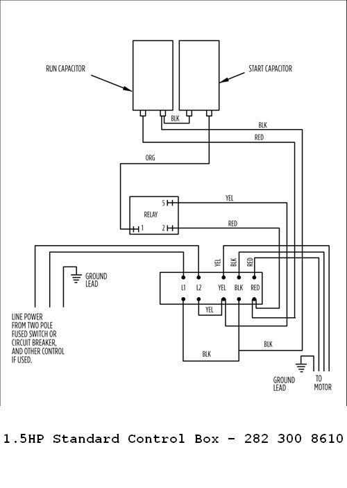
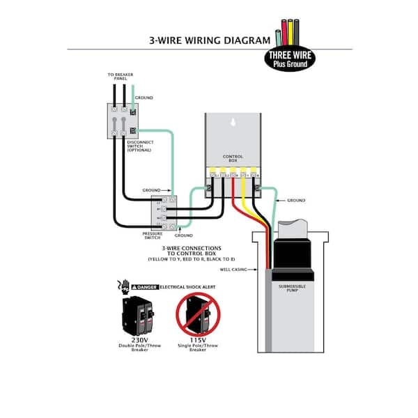
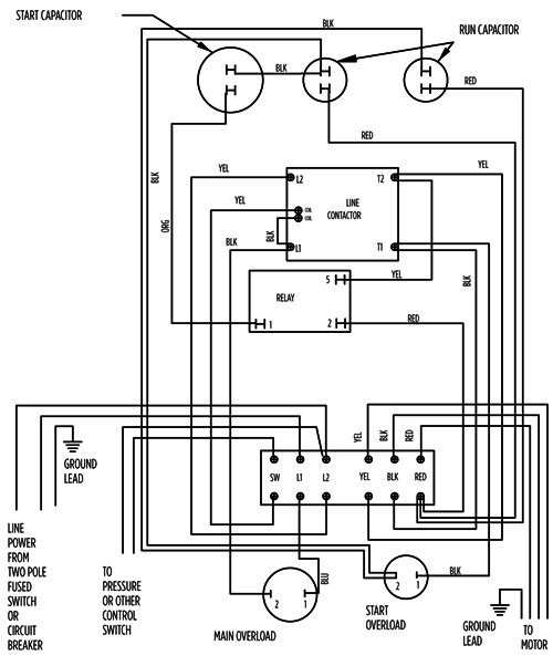
When it comes to ensuring the efficient operation of your well pump, having a clear understanding of the control box wiring diagram is paramount. This diagram serves as a blueprint for the electrical connections that power and regulate the pump, ultimately influencing its performance and longevity. By delving into the intricacies of the wiring diagram, individuals can troubleshoot issues, make repairs, and even optimize the system for enhanced functionality. Let’s explore the value of a well pump control box wiring diagram in detail.
Understanding the Basics
At the core of any well pump control box wiring diagram lies a set of essential components that work together to facilitate the operation of the pump. These components typically include the control box itself, the pressure switch, the pump motor, and various electrical connections. Each component plays a crucial role in regulating the flow of electricity and ensuring that the pump functions as intended.
Components of a Control Box Wiring Diagram
Control Box: Acts as the central hub for electrical connections and houses the necessary components.
Pressure Switch: Monitors water pressure and triggers the pump to turn on or off accordingly.
Pump Motor: Responsible for driving the pump and generating the necessary hydraulic pressure.
Electrical Connections: Include wires, terminals, and connectors that link the components together.
Troubleshooting and Maintenance
One of the primary benefits of having a well pump control box wiring diagram at your disposal is the ability to troubleshoot and perform maintenance tasks effectively. By referencing the diagram, individuals can pinpoint potential issues, such as faulty connections or damaged components, and take the necessary steps to rectify them. Regular maintenance based on the wiring diagram can also help prevent major malfunctions and extend the lifespan of the pump system.
Common Issues and Solutions
No Power to the Pump: Check the electrical connections and the control box for any loose wires or blown fuses.
Inconsistent Pump Operation: Inspect the pressure switch and motor connections for signs of wear or damage.
Overheating Motor: Ensure proper ventilation and cooling for the pump motor to prevent overheating issues.
Optimizing Performance
Beyond troubleshooting and maintenance, a well pump control box wiring diagram can also be used to optimize the performance of the pump system. By understanding the electrical layout and connections, individuals can make adjustments to enhance efficiency, reduce energy consumption, and improve overall functionality. This proactive approach can lead to cost savings and a more reliable water supply.
Performance Enhancement Tips
Upgrade to high-quality wiring components for better conductivity and durability.
Adjust the pressure switch settings to fine-tune the pump operation according to water demand.
Implement a regular inspection schedule to detect and address any potential issues proactively.
Conclusion
In conclusion, a well pump control box wiring diagram is a valuable resource that empowers individuals to maintain, troubleshoot, and optimize their well pump systems. By familiarizing yourself with the diagram and following best practices for wiring and maintenance, you can ensure the smooth operation of your pump and prolong its lifespan. Invest time in understanding the intricacies of the wiring diagram, and reap the benefits of a reliable and efficient well pump system.
Related to Well Pump Control Box Wiring Diagram
- Warn Winch Solenoid Wiring Diagram
- Warn Winch Wiring Diagram
- Warn Winch Wiring Diagram 4 Solenoid
- Water Heater Wiring Diagram
- Water Well Pump Wiring Diagram
Submersible Pump Control Box Wiring Electrician Idea
The image title is Submersible Pump Control Box Wiring Electrician Idea, features dimensions of width 600 px and height 300 px, with a file size of 600 x 300 px. This image image/jpeg type visual are source from www.electricianidea.com.
Franklin Electric 1 1 2 Or 1HP 230V Control Box W Overload
The image title is Franklin Electric 1 1 2 Or 1HP 230V Control Box W Overload, features dimensions of width 500 px and height 703 px, with a file size of 500 x 703 px. This image image/jpeg type visual are source from www.wwpp.co.
ECO FLO 1 2 HP Control Box For 4 In Well Pump EFCB5 HD The Home Depot
The image title is ECO FLO 1 2 HP Control Box For 4 In Well Pump EFCB5 HD The Home Depot, features dimensions of width 600 px and height 600 px, with a file size of 600 x 600. This image image/jpeg type visual are source from www.homedepot.com.
Franklin Electric 5HP 230V Deluxe Control Box
The image title is Franklin Electric 5HP 230V Deluxe Control Box, features dimensions of width 500 px and height 602 px, with a file size of 500 x 602. This image image/png type visual are source from www.wwpp.co.
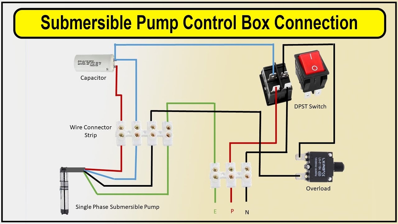
How To Make Submersible Pump Control Box Connection Wiring Diagram Submersible Pump YouTube
The image title is How To Make Submersible Pump Control Box Connection Wiring Diagram Submersible Pump YouTube, features dimensions of width 1280 px and height 720 px, with a file size of 1280 x 720. This image image/jpeg type visual are source from m.youtube.com
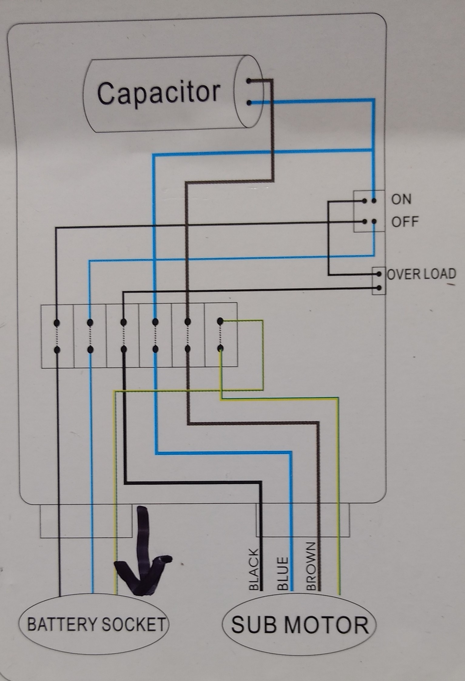
Plumbing Confusion About Wiring Control Box For A Submersible Well Pump Home Improvement Stack Exchange
The image title is Plumbing Confusion About Wiring Control Box For A Submersible Well Pump Home Improvement Stack Exchange, features dimensions of width 1533 px and height 2241 px, with a file size of 1533 x 2241. This image image/jpeg type visual are source from diy.stackexchange.com.
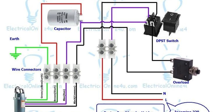
Submersible Pump Control Box Wiring Submersible Pump Well Pump Electrical Diagram
The image title is Submersible Pump Control Box Wiring Submersible Pump Well Pump Electrical Diagram, features dimensions of width 735 px and height 386 px, with a file size of 735 x 386. This image image/jpeg type visual are source from www.pinterest.com.
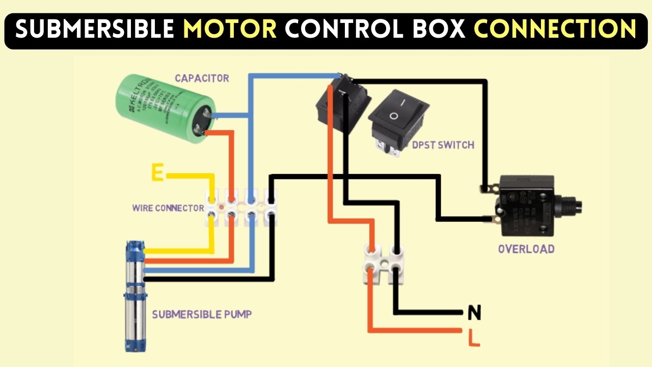
Submersible Pump Control Box Wiring Diagram For 3 Wire Single Phase YouTube
The image title is Submersible Pump Control Box Wiring Diagram For 3 Wire Single Phase YouTube, features dimensions of width 1280 px and height 720 px, with a file size of 1280 x 720.
The images on this page, sourced from Google for educational purposes, may be copyrighted. If you own an image and wish its removal or have copyright concerns, please contact us. We aim to promptly address these issues in compliance with our copyright policy and DMCA standards. Your cooperation is appreciated.
Related Keywords to Well Pump Control Box Wiring Diagram:
submersible pump control box wiring diagram,submersible pump control panel wiring diagram,water pump control box wiring diagram,water pump control panel wiring diagram,well pump control box wiring diagram
